


RF400 Series Spread Spectrum Data Radio/Modems
24
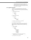
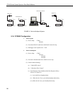
2. Point-to-multipoint
a. Complete steps 1 to 4 above making the remote stations’ Network
Addresses and Hopping Sequences the same as the base station’s.
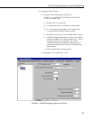
b. While in Standard Setup verify that the active interface is “Auto
Sense” and give each remote RF400 a unique Radio Address.
You should label each RF400 (with masking tape) indicating the
configured network address, radio address, hopping sequence, etc.
c. Exit and Save your configuration by pressing “5”.
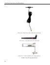
3. Antenna considerations
a. Line of sight – the single most important factor in radio performance
is antenna placement. As Appendix H states, “height is everything.”
The two RF400s must be able to ‘see’ each other if distances over a
mile or two are required. This can be accomplished with a mast or
tower.
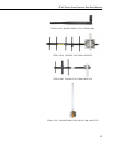
b. Mounting – the higher the gain of a yagi antenna, the more important
it is to aim the yagi precisely and mount the yagi solidly to prevent
movement due to strong winds, large birds, etc.
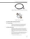
c. Antenna cable routing – the antenna cable should be routed in a
protected area and made secure against damage from wildlife, wind,
and vandalism.
d. Antenna cable weather sealing – the presence of water inside the
antenna cable’s plastic sheath can attenuate your transmitted and
received signals significantly. The RF energy, instead of traveling
the length of the cable with little loss, is absorbed according to the
amount of water present (like in a microwave oven). A small amount
of water can ruin a once good communication link.
When moisture gets inside the sheath it is very difficult to remove.
Some careful cable handling (even pinholes can let in significant
amounts of water), thoughtful cable routing, and good weather-
proofing can prevent this.
Apply a 1/8 inch thick coat of pure silicone rubber compound (RTV)
1) where the cable connector screws onto the antenna connector
(apply after the connector is in place allowing future removal) and
2) at the junction between plastic cable sheath and cable connector. If
carefully done this should last for years. An alternative approach is to
wrap self-vulcanizing rubber tape around these same areas of the
antenna connector, cable connector and cable sheath. This tape can
be purchased at most electrical supply stores (see Troubleshooting
Section 6, item 6).
4. Site considerations
Location of an RF400 near commercial transmitters, such as at certain
mountaintop sites, is not recommended due to possible “de-sensing”
problems for the RF400 receiver. A powerful signal of almost any
frequency at close range can simply overwhelm a receiver. Lower