


RF400 Series Spread Spectrum Data Radio/Modems
7
Auto Sense
The RF400 has a default feature called “Auto Sense” that automatically
configures certain RF400 settings. When you connect an RF400 to a
datalogger (CS I/O port to CS I/O port) the RF400 detects the presence of the
datalogger and makes its CS I/O port the active port. When you are not
connected to a datalogger’s CS I/O port, Auto Sense detects that and
configures its RS-232 port as the active port and configures certain other
settings so it can serve as a base RF400.
For point-to-point networks Auto Sense and default settings take care of
everything. An exception to this is where you have a neighboring network that
is also using the default RF400 settings. In this case, refer to Software Setup
Section 5 and change your RF400s to a hopping sequence different than the
default settings of “0” (zero). For this point-to-point network, configure both
RF400s the same.
Radio Address
Each RF400 has a “Radio Address” that can be changed by the user. In order
for two RF400s to communicate, their radio addresses must be set to the same
number. The RF400’s factory default radio address is “0” (zero) so a pair of
RF400s will be able to communicate out of the box (their network addresses
and hopping sequences are also “0” (zero) by default). See Section 4.1.3.1 and
Section 5 (Software Setup) for more details.
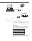
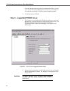
Step 4 – Connect
You are now ready to Connect to your datalogger using the
LoggerNet/PC208W Connect screen. After you connect, notice the flashing of
the green LEDs on both RF400s. This indicates that RF packets with the same
hopping sequence are being received by the RF400s. The red LEDs light solid
while the connection lasts. When you Disconnect, the red LEDs remain on for
five seconds, which is the default setting of the “Time of Inactivity to Sleep.”
Datalogger program transfer and data collection are now possible. Refer to
Appendix H for a treatment of communication distance vs. factors in the RF
path.
4. System Components
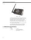
4.1 RF400 Series Data Radios
4.1.1 Indicator LEDs
The RF400 has a red LED labeled “Pwr/TX” and a green LED labeled “RX.”
When 12V power is applied the red LED lights for ten seconds. About 5
seconds after power-up the green LED lights for a second. Ten seconds after
power-up the selected standby mode begins to control the red LED. The red
LED lights to indicate when the receiver is actively listening. When the
receiver detects RF traffic (header or data with the same hopping sequence),
the red LED will light steadily. When the RF400 is transmitting, the red LED
will pulse OFF as the RF packets are transmitted (it will not be on solid).