


Appendix K. RF400/RF410 Pass/Fail Tests
K-3
TESTING RF400/RF410s
After verifying the functionality of the terminal program and the integrity of
the serial cable and COM port, proceed as follows:
(1) Connect 12V power to an RF400/RF410. This can be from an AC adapter
(Item # 14220 or Field Power Cable (Item # 14291) with 12V battery pack
attached (see step 12 below).
(2) Connect first RF400/RF410’s RS-232 port to the PC COM port
(3) Run a terminal program such as HyperTerminal
TM
or Procomm
TM
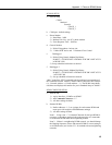
(a) Baud rate: 9600
(b) Data, Parity, Stop Bits: 8-N-1
(c) Flow control: none
(d) Emulation: TTY
(e) ASCII
(f) Desired COM port
Make sure that Properties/Settings/ASCII Setup “Echo characters
locally” or the equivalent Procomm
TM
setting is NOT enabled.
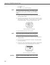
(4) Press “Program” button on RF400/RF410
(5) Select “3” to restore defaults, then select “5” to save parameters and exit
The presence of a neighboring RF400/RF410 network with
default settings could interfere with your tests (see Section 5.3.1.
(4.d) for detection method).
(6) Repeat steps 1 to 5 inclusive with second RF400/RF410
(7) Label the RF400/RF410 connected to the PC COM port as “Base”
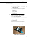
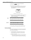
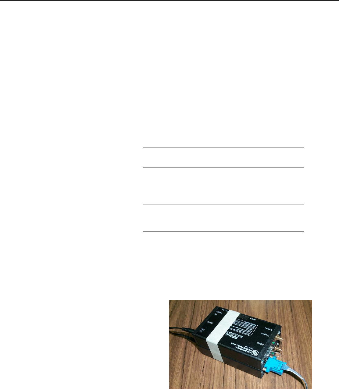
(8) Place the two RF400/RF410s side by side with antenna connectors 1 1/8
inches apart on a non-metallic surface (see Figure K-1).
FIGURE K-1. Loop-back Test without Antennas
NOTE
NOTE