


Appendix K. RF400/RF410 Pass/Fail Tests
K-4
(9) Make sure that no antennas are attached to the RF400/RF410s
(10) Label the other RF400/RF410, “Remote”
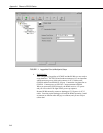
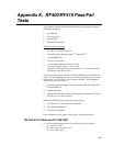
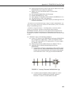
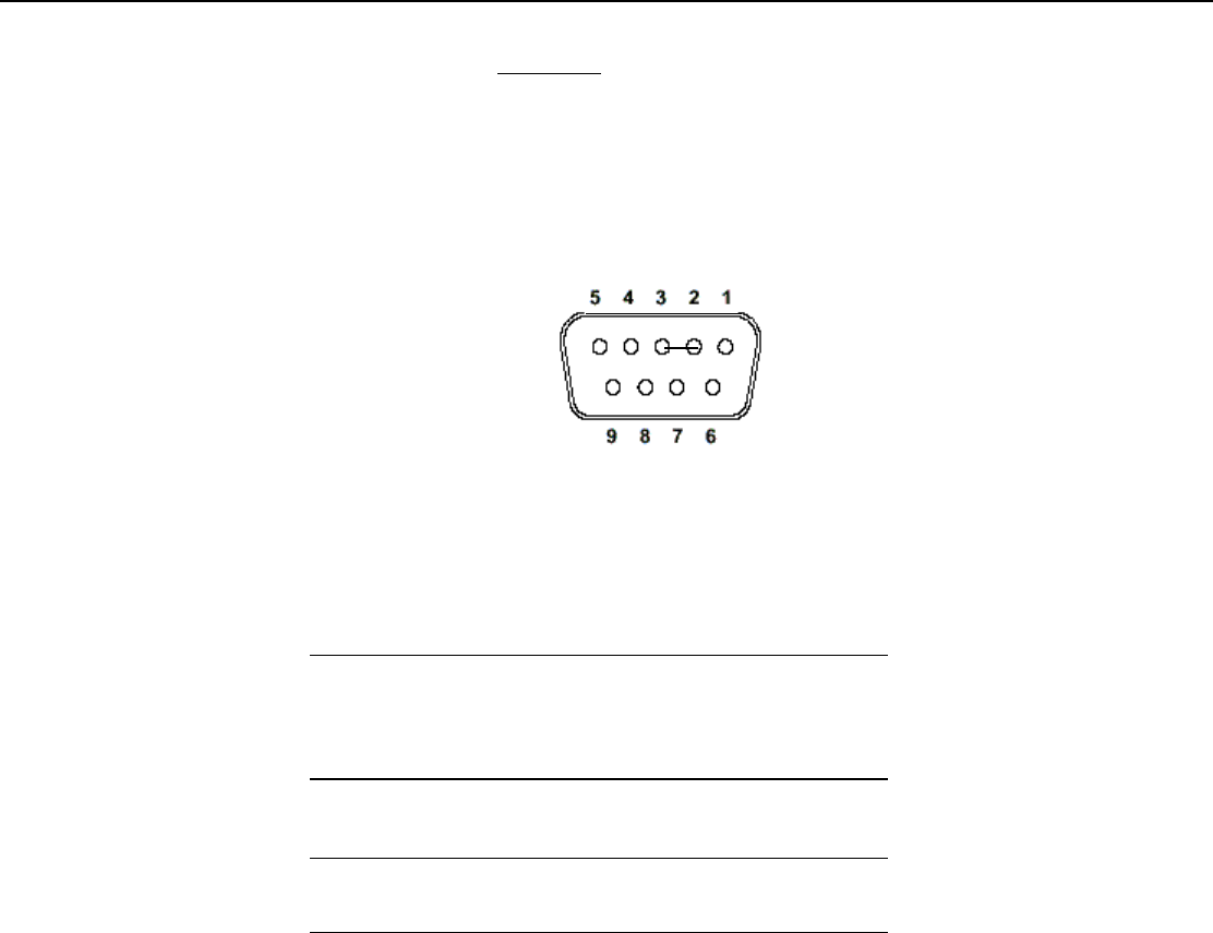
(11) Insert jumper into the Remote RF400/RF410’s RS-232 connector pins 2
and 3 (using a U-shaped portion of a paper clip) allowing data received
from base RF400/RF410 to be transmitted back to terminal screen by
remote RF400/RF410.
RF400/RF410’s RS-232 Connector (female)
(12) Connect 12V power to Remote RF400/RF410. This can be supplied by an
AC adapter (Item # 14220) or Field Power Cable (Item # 14291)
connected to a 12V battery (battery can be an 8 cell pack of alkaline A, C,
or D cells, or a lead-acid battery).
If your 12V power supply is a battery pack or rechargeable
battery, make sure that the batteries are fresh or well-charged so
they can supply the 75 mA peak current needed when the
RF400/RF410 is transmitting in order to obtain valid test results.
For safety, people should maintain 20 cm (8 inches)
distance from antenna while RF400/RF410 is transmitting.
(13) Type 8 groups of 5 characters on the terminal (aaaaabbbbbccccc etc.)
(14) You should see 100% of the characters typed echo back to the screen
TESTING ANTENNAS
After setting up the terminal program and verifying the integrity of the COM
port, serial cable, and RF400/RF410s, you are ready to test an RF400/RF410
antenna. Prepare to test an antenna by:
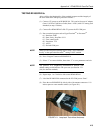
• Orienting RF400/RF410s so that the antenna connectors are on top
• Fastening RF400/RF410s to cardboard boxes or other non-metallic
structures maintaining antenna connectors 20 inches above the floor.
(1) TESTING ¼ Wave Antenna
(a) Connect 12V power to base RF400/RF410 and remote RF400/RF410.
We recommend AC adapter Item # 15966 or a Field Power Cable
Item # 14291 connected to a 12V battery pack or 12V power supply.
1
NOTE
CAUTION