


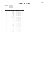


1.
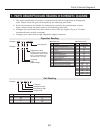
PARTS DESCRIPTION AND READING IN SCHEMATIC DIAGRAM
1. The parts specification of resistors, capacitors and coils are expressed in designated
code. Please check the parts description by the following code table.
2. Some of transistors and diodes are indicated in mark for the substitution of parts
name. Please check the parts name by the following code table.
3. Voltages and waveforms were taken with a video color bar signal (1Vp-p at 75 ohms
terminated) and controls to normal.
4. Voltages were taken with a high-impedance digital voltmeter.
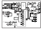
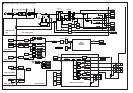
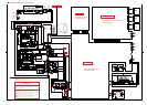
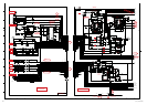
Part 6: Electrical Diagrams
6-1
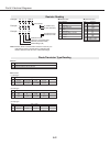
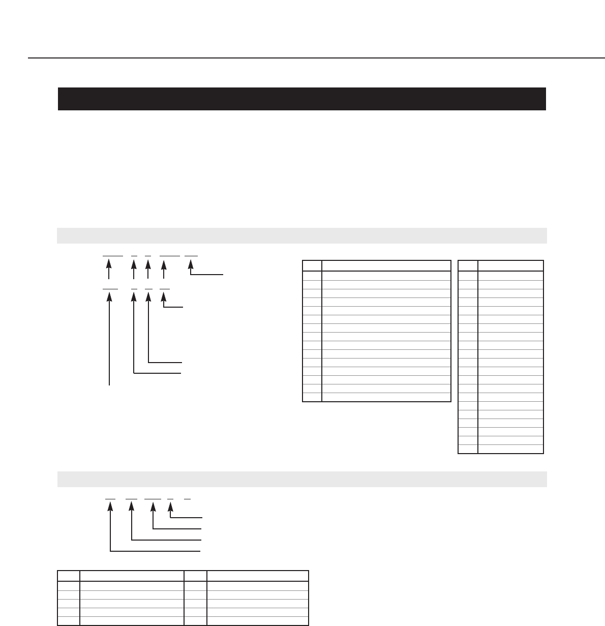
Example 2000 K K 1000 BG
Characteristic
Example 160 E M 10
Capacitance value
Tolerance
Type
Rated voltage
Excepting electric capacitors,
all capacitance values of less
than 1 are expressed in µF
and more than 1 are in pF.
Capacitor Reading
Mark Material
E Electrolytic
P Electrolytic (non-polarized)
C Ceramic (temperature compensation)
K Ceramic
F Polyester
N Polypropylene
M Metalized polypropylene
H Metalized polypromylar
B Ceramic (semiconductor)
G Metalized polyestel
Y Composite film
S Styrol
T Tantalum oxide solid electrolytic
U Organic semiconductive electrolyte
D Electric double layer electrolytic
Mark Tolerance
A not specified
B ±0.1
C ±0.25
D ±0.5
F±1
G±2
E ±2.5
H±3
J±5
K±0
M±20
N±30
P +100 -0
Q +30 -10
T +50 -10
U +75 -10
V +20 -10
W +100 -10
X +40 -20
Y +150 -10
Z +80 -20
● Material table
● Tolerance table
Example L2 C1 4R7 K N
Tolerance
Inductance value
Manufacture code
Unique code
Mark Tolerance (nH) Mark Tolerance (%)
C ±0.25 G ±2
D ±0.5 J ±5
S ±0.3 K ±10
A ±0.2 L ±15
M±20
Coil Reading