


3. MECHANICAL DISASSEMBLIES
Mechanical disassemble should be made following procedures in numerical order.
Following steps show the basic procedures, therefore unnecessary step may be
ignored.
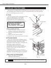
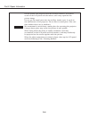
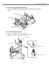
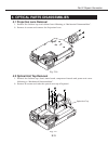
3.1 Cabinet Top Removal
(1) Remove 5 screws.
(2) Remove 2 screws A of the
Cabinet Front (bottom
part). See Fig. 2-5
(3) Pull the lower part of the
Cabinet Front off forward.
(4) Pull the Cabinet Top upward
while opening the
arrow indicated part of it
toward outside.
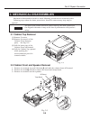
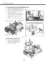
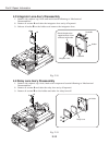
3.2 Cabinet Front and Speaker Removal
1. Remove 4 screws (2 top and 2 bottom) A and take the cabinet front off forward.
2. Remove 2 screws B and then remove RC board and temp board.
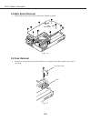
3. Remove 4 screws C and the speaker.
Part 2: Repair Information
2-5
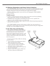
CAUTION
The parts and screws should be placed exactly the same position as
the original otherwise it may cause loss of performance and product
safety.
Fig. 2-4
C
A
A
A
RC Board
A
Temp Board
B
B
Fig. 2-5