


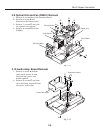
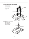
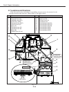

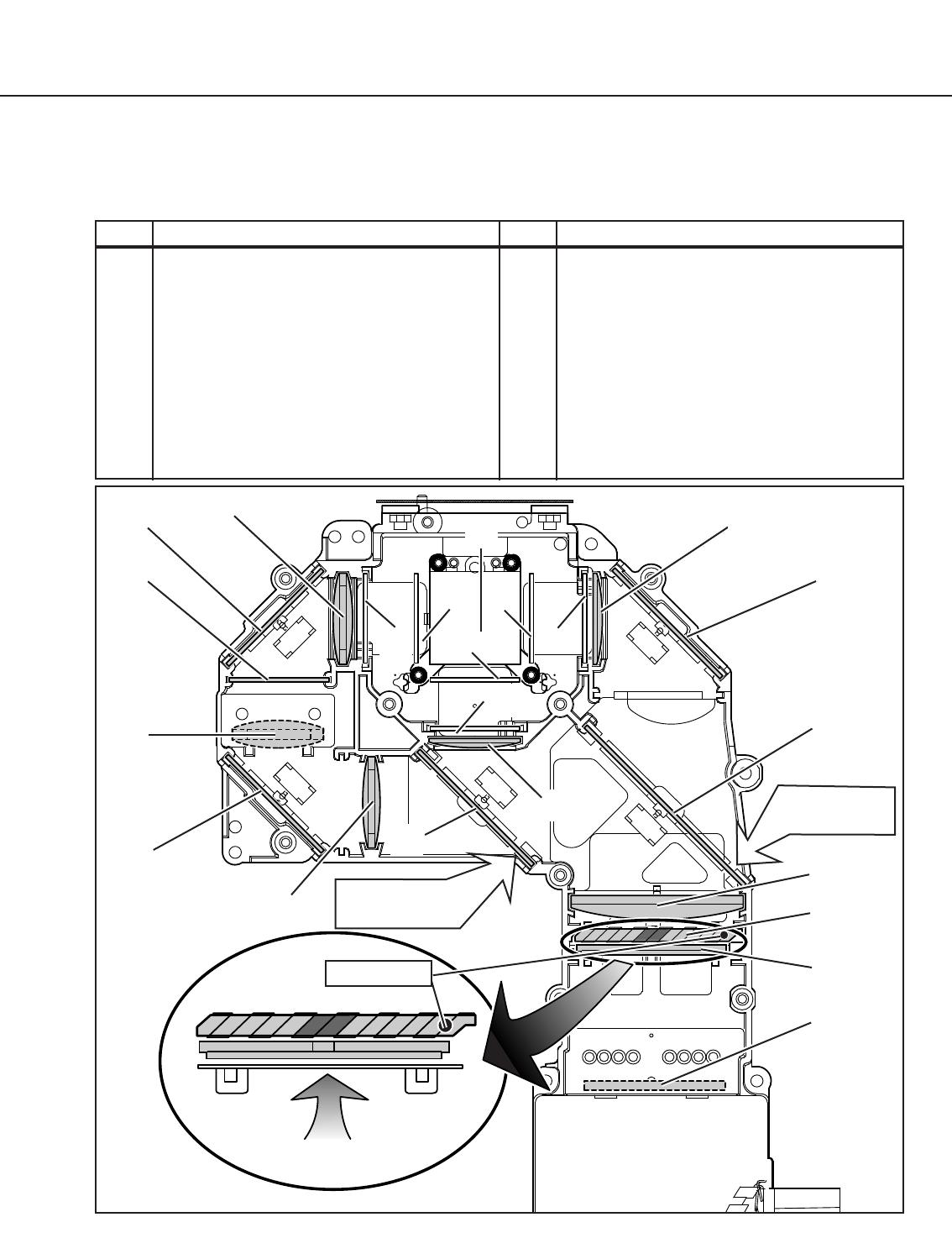
4.7 Locations and Directions
When the optical parts mounting or assembling, the parts must be mounted in the
specified location and direction. Please follow to the figure below.
Part 2: Repair Information
2-14
1 Prism ass’y 12 Relay lens (OUT)
2 Integrator lens (IN) 13 Relay lens (IN)
3 Integrator lens (OUT) 14 Dichroic mirror (G)
4 Prism Ass’y (PBS) 15 Condenser lens
5 Condenser lens (OUT) 16 Polarized glass (OUT/R)
6 Dichroic mirror (R) 17 Polarized glass (OUT/G)
7 Mirror (R) 18 Polarized glass (OUT/B)
8 Condenser lens (R) 19 Polarized glass (IN/R)
9 Condenser lens (B) 20 Polarized glass (IN/G)
10 Mirror (B) 21 Polarized glass (IN/B)
11 Optical Filter (UV cut)
No. Part name No. Part name
Fig. 2-22
A cutting corner
comes this side up.
1
13
3
14
12
17
18
2
16
4
6
10
10
9
A cutting corner
comes this side up.
5
7
11
15
19
21
20
Light Source
Dot marker
8