


Part 3: Adjustment
3-5
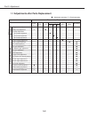
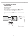
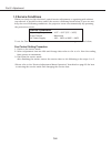
1.4
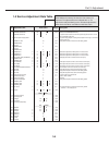
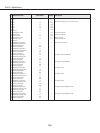
Service Adjustment Data Table
PC CV or S Y/Cb/Cr
0 RGB AMP (Gamma OFF)
✻
30 30 0 - 63 Same as No.1of RGB AMP(Gamma ON)
1 RGB AMP (Gamma ON) 30 30 To up/down R/G/B of Gamma at same time system stop up/down, when R, G or B
value reached Max or Min value.
2 S&H Test pattern display position 3 0 - 12 Test pattern display depend on setting value,test pattern move to right, 1 dot each by
increasing data value.
3 GAMMA DLY CNT
✻
25 0 - 63 Display Green test pattern where Service No2 setting position.
4 GAMMA G BIAS 5 0 - 63
5 Not used
6 GAMMA R BIAS 5 0 - 63
7 Not used
8 GAMMA B BIAS 5 0 - 63
9 GAMMA R-B1P
✻
27 28 28 0 - 63 White balance adjustment of Black portion in AV mode for Red
10 GAMMA B-B1P
✻
27 28 28 0 - 63 White balance adjustment of Black portion in AV mode for Blue
11 GAMMA G-B1P 27 28 28 0 - 63 White balance adjustment of Black portion in AV mode for Green
12 DAC CLAMP LEVEL(SUB BRIGHT)
✻
30 30 0 - 63 Sub-Bright(refer to DAC IC Control and User control spec)
13 GAMMA R GAIN
✻
30 30 0 - 63
14 GAMMA B GAIN
✻
30 30 0 - 63
15 DAC RGB BIAS
✻
50 50 0 - 125 G-Bias adjust value(refer to DAC IC Control and User control spec)
16 DAC R BIAS
✻
50 50 50 0 - 125 R-Bias adjust value(refer to DAC IC Control and User control spec)
17 DAC B BIAS
✻
50 50 50 0 - 125 B-Bias adjust value(refer to DAC IC Control and User control spec)
18 DAC RGB GAIN(SUB CONTRAST) 20 30 0 - 63 Sub-CONT(refer to DAC IC Control and User control spec)
19 S&H B-CK 12 0 - 255 Display Blue test pattern where Service No2 setting position.
20 S&H G-CK 12 0 - 255 Display Green test pattern where Service No2 setting position.
21 S&H R-CK 12 0 - 255 Display Red test pattern where Service No2 setting position.
22 Setting for Shoot out mode 0 0 - 2 0;Normal/ 1;Shoot out1/ 2;Shoot out2
23 Serial baud rate setting 1 0 - 2 0;9600/ 1;19200/ 2;38400
24 Lamp life time display 0 Read Only
25 S&H HCK PHASE adjust 4 0 - 15 Display Green test pattern where Service No2 setting position.
26 GAMMA R_WHP 57 57 57 0 - 63
27 GAMMA G_WHP 57 57 57 0 - 63
28 GAMMA B_WHP 57 57 57 0 - 63
29 Fan Control
✻
0 0 or 1 Fans control for high land, control FAN_CONT1/FAN_CONT2.
0 : automatic, 1 : Forced High speed
30 D/A gain
✻
128 128 128 0 - 255
NTSC PAL
36 VD Analog Cont3(CV) 72 0 - 255
37 VD Analog Cont4 0 0 - 255
42 VD Bright 148 130 0 - 255
43 VD Contrast 68 68 0 - 255
64 VD Analog Cont3(S-Video) 72 0 - 255
PC Y/Cb/Cr
272 REDGAIN 96 96 0 - 255
273 GRNGAIN
✻
96 96 0 - 255
274 BLUGAIN
✻
96 96 0 - 255
275 REDOFST
✻
32 0 - 63
276 GRNOFST
✻
32 0 - 63
277 BLUOFST
✻
32 0 - 63
278 CLDUR -- -- 0 - 255
279 CLPLACE -- -- 0 - 255
No. Adjustment Item RangeInitial Value Description
These initial values are the reference data written from the
CPU ROM to the memory IC when the new memory IC
replaced. The adjustment items indicated with “✻” are
required to readjust following to the “Electrical adjustments”.
Other items should be used with the initial data value.