


Field Test Unit Software
7.
FTUC
COMMANDS
7.1
DISPLAY
FORMAT
The display of the
FTU
has three formats available. These formats can be
selected at the touch of a button. Normally as many bytes as possible are dis-
played on the screen at all times. For example
-
if you were displaying the
contents of the logger memory as single bytes then four bytes could be dis-
played per screen line, making a total of eight bytes displayed (only the top
two lines of the display are used for display purposes).
The three formats available are:
7.2 DISPLAY OF THE LOGGERS CURRENT MEMORY VALUES
In this format the values are not scaled and as displayed as a number from
O-255. Eight values are displayed across the screen and they represent the
current selected memory address location followed by the successive seven
memory locations. The current memory location can be changed using
keystrokes outlined later. This display format is the default when the FTU
is
first
powered up and the logger connected.
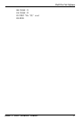
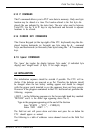
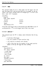
EXAMPLE: When first powered up and connected the FTU will display the
following (or similar):
10300
x4400
Address = 0
The ‘10’ is the version of logger connected. (Memory location 0)
The ‘3’ is the
runtime
of the program in the logger. (Memory location 1)
The ‘0’s” are memory locations not used.
The
‘X’
represents a value that will change on your screen. This is Memory
Location 4 and is where the logger shows the current clock value.
The ‘44” is also a changing value and is related to your loggers clock value
(Memory Location 6) [See Hardware Supplement 6200 for further details
of the logger’s memory locations].
32
Section 7. FTUC COMMANDS