


6
39
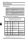
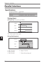
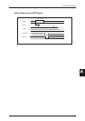
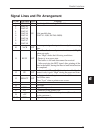
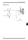
Signal Lines and Pin Arrangement
Pin No.
Signal Name Direction
Function
1 *STROBE IN Synch signal for reading DATA 1-8.
2 DATA1
3 DATA2
4 DATA3
5 DATA4 IN 8-bit parallel data
6 DATA5 (DATA1: LSB, DATA8: MSB)
7 DATA6
8 DATA7
9 DATA8
10 *ACK OUT
Data request signal output when ready for receiving
data.
Goes “Low” when ready to receive data, and “High”
when not ready.
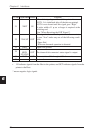
Goes “High” under the following conditions.
11 BUSY OUT • Printer is in an error state.
• The buffer is full and data cannot be received.
• After receiving the INIT signal, after printing of the
data in the buffer, during the interval until initialization
is completed.
12 PE OUT
In the case that “Paper End” detection is enabled by the
control code, it goes “High” during the paper end state.
13 SELECT OUT
Indicates whether the printer is in the Online state or
the Offline state.
Goes “Low” when a printer error occurs.
14 Not used.
15 Not used.
16 GND Signal line ground.
17 FG Connected to the printer case.
18 +5V
Connected to +5 V inside the printer. (Cannot be used
by the customer.)
19-30 GND Signal line ground.
Parallel Interface