User’s Guide 21020285 D
Chapter 8 Details of Usage
Byte and Word Swapping Page 8 - 5
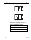
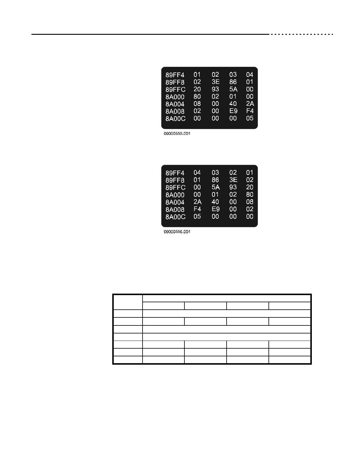
If written to VME memory in the order given above, these command parameters
would be written differently (as shown below) for both types of processors:
Figure 19 Intel Ordering
Figure 20 Motorola Ordering
It becomes apparent when examining the memory displays, that the Command
Structures of the RF3880 though divided into a variety of byte, word, and
double-word fields, must be considered as a grouping of double-words.
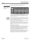
In a Motorola environment, the Parameter Block would remain as graphically
represented throughout this manual, and as shown below:
Address
Offset
Byte Memory Address
Offset + 0 Offset + 1 Offset + 2 Offset + 3
00H Command Identifier - 04030201H
04H Flags-2 = 01H Flags-1 = 86H Addr. Mod = 3EH Target ID = 02H
08H VME Memory Address - 005A9320H
0CH Transfer Count = 00010280H
10H 0 = 2AH 1 = 40H 2 = 0 3 = 08H
14H 4 = F4H 5 = E9H 6 = 0 7 = 02H
18H 8 = 05H 9 = 0 10 = 0 11 = 0
Table 111: Motorola Ordered Parameter Block


