


3-2
Book Title
78-13113-06 B0
Chapter 3 Installing and Removing the Uplink Cards
Preparing for Installation
Preparing for Installation
Please read the following instructions when preparing to remove an uplink card from the
Cisco 10720 Internet Router:
• Powering Down the Router, page 3-2
• Verifying That the Router Is Powered Down, page 3-4
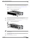
• Removing the Cable-Management System, page 3-4
• Removing the Cable-Management System, page 3-4
Go to the “Powering Down the Router” section on page 3-2 to continue the uplink card removal
procedure.
Powering Down the Router
Follow the steps in this section to power down the router and disconnect the site power.
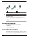
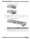
Step 1 If the cable-management cover is installed on the router, it must be removed in order to access the power
switch. (See the “ •Removing the Cable-Management System, page 3-4” section on page 3-2.) Do not
remove the cable-management tray until all cables are removed from the cards and power supply.
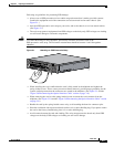
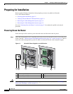
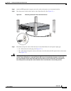
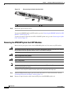
Figure 3-1 AC and DC Power Supplies in the Off Position
Caution Use an ESD-preventive strap when disconnecting power leads on the router. See the “Preventing
Electrostatic Discharge” section on page 2-4.
1 Power on symbol (–) 3 AC power switch
2 Power off symbol (O) 4 DC power switch
IN OK
DC
OTF
IN OK
DC
OTF
IN OK
DC
OTF
IN OK
DC
OTF
57855
3
4
1 2