


3-20
Book Title
78-13113-06 B0
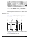
Chapter 3 Installing and Removing the Uplink Cards
Turning On Power to the Router
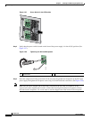
Figure 3-27 Power Switch in the Off Position
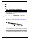
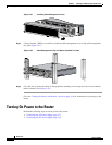
Step 3
Verify that the power switch located on the front of the power supply is in the off (O) position. (See
Figure 3-27.)
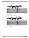
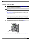
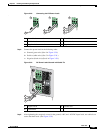
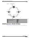
Figure 3-28 Tightening the DC Lead Receptacle
Step 4
Insert the stripped end of the ground lead all the way into the ground lead receptacle on the DC-input
power supply and tighten the receptacle screw using a 1/8-inch flat-blade screwdriver. (See Figure 3-28.)
Note Make sure the entire stripped end of each lead is inserted all the way into its receptacle. If any
exposed wire at the stripped end of a lead is visible after inserting the lead into its receptacle, remove
the lead from the receptacle. Use a wire cutter to cut the stripped end of the lead to fit the receptacle.
IN OK
DC
OTF
IN OK
DC
OTF
57872
1 Ground lead
122053
1