


3-12
Book Title
78-13113-06 B0
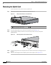
Chapter 3 Installing and Removing the Uplink Cards
Connecting the Ports on the RPR/SRP, DPT, and POS/DPT Uplink Cards
Warning
Class 1 laser product.
Warning
Class 1 LED product.
Warning
Because invisible radiation may be emitted from the aperture of the port when no fiber cable is
connected, avoid exposure to radiation and do not stare into open apertures.
Note The fiber-optic connectors must be free of dust, oil, and other contaminants. Carefully clean the
fiber-optic connectors using a fiber cleaning kit. For information about cleaning, see the Inspection
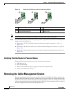
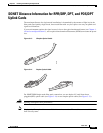
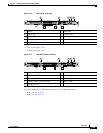
and Cleaning Procedures for Fiber-Optic Connections document.Four-Node DPT Ring Using the DPT
Uplink Card—RX and TX Connections
Connecting the Ports on the RPR/SRP, DPT, and POS/DPT Uplink
Cards
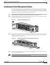
Before connecting the ports on a RPR/SRP, DPT, or POS/DPT uplink card, install the cable-management
system. For more information, see the “Installing the Cable-Management System” section on page 3-15.
The cable and connection specifications are located in Chapter 1, “Overview and Specifications.”
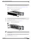
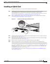
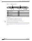
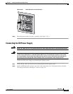
Figure 3-15 Attaching the Optical Interface Cable
Step 1 Attach optical interface cables to the uplink card. (See Figure 3-15.)
Use a single-mode interface cable to connect the router to another router or switch. If you are connecting
to a DPT network, the two ports represent the two sides of a single SRP connection:
1 Optical interface cable connector
1
1. The left side of the port is TX, and the right side of the port is RX. Each card contains two ports. In this example, a duplex
cable is shown.
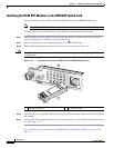
RESET
CONSOLE
AUX
OVERTEMP
ACTIVE
CARD FAIL
SYSTEM STAUS
POWER
CARRIER
RX PKT
WRAP
PASS THRU
66302
1