


CHAPTER
4-1
Book Title
78-13113-06 B0
4
Creating a Four-Node Ring Using the Uplink Cards
This chapter provides information for creating a four-node ring, either DPT or IEEE 802.17 RPR, using
the DPT or RPR/SRP uplink cards.
DPT Uplink Card
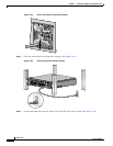
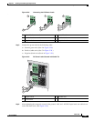
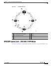
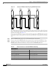
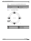
Use Figure 4-1 and Table 4-1 to help organize the cable connections for a four-node DPT ring.
Create a four-node DPT ring by connecting the fiber-optic cables to DPT uplink cards that are installed
in routers on the network.
Figure 4-1 Creating a Four-Node DPT Ring Using DPT Uplink Cards
The TX side B port on Node 1 goes to the RX side A port on the next router, which will become Node
2. The labels above the fiber connectors identify side A (left port) TX and RX, and side B (right port)
TX and RX. (See Figure 4-1 and Table 4-1.)
To create a four-node DPT ring, perform the following steps:
Node 1Node 4
ACTIVE
CARRIER
RX PKT
WRAP
PASS THRU
A B
10720-SR-LC
TX RX TX RX
ACTIVE
CARRIER
RX PKT
WRAP
PASS THRU
A B
10720-SR-LC
TX RX TX RX
Node 2
ACTIVE
CARRIER
RX PKT
WRAP
PASS THRU
A B
10720-SR-LC
TX RX TX RX
Node 3
ACTIVE
CARRIER
RX PKT
WRAP
PASS THRU
A B
10720-SR-LC
TX RX TX RX
Tx
Rx
Tx
Rx
Tx
Rx
Tx
Rx
Tx
Rx
Tx
Rx
Tx
Rx
Tx
Rx
57876