


3-5
Book Title
78-13113-06 B0
Chapter 3 Installing and Removing the Uplink Cards
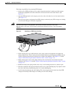
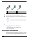
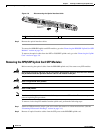
Removing the Cable-Management System
Note It is not necessary to remove the cable-management tray in order to install or remove an uplink card.
Only the cable-management cover must be removed in order to install or remove an uplink card.
If the cable-management cover is not installed, go to the “Powering Down the Router” section on
page 3-2.
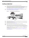
Perform the following steps to remove the cable-management cover:
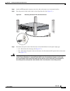
Figure 3-4 Removing the Cable-Management Cover
Step 1 Verify that all cables are safely secured before detaching the cable-management cover.
Step 2 Use a Number 1 Phillips screwdriver to loosen and unscrew the captive installation screws holding the
cable-management cover to the router.
Step 3 Remove the cable-management cover from the router. (See Figure 3-4.)
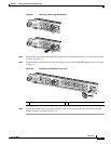
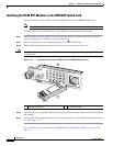
Figure 3-5 Removing the Cable-Management Tray
Caution To avoid accidental damage to router cables or card ports, remove all cables before removing the
cable-management tray.
Step 1 Use a Number 1 Phillips screwdriver to remove the screws holding the cable-management tray to the
router. (See Figure 3-5.)
Step 2 Lift the cable-management tray from the router.
A
C O
K
D
C O
K
OTF
A
C O
K
D
C O
K
O
TF
IN
PUT 100-200- 50/60Hz 2-5A
DON NOT REMOVE
OR INSERT CABLES
WITH THE POWER ON
C
AR
D FA
IL
C
A
R
D
F
A
IL
L
IN
K
/A
C
T
IV
E
(G
)
1
0
0
M
B
P
S
PO
W
E
R
RESET
CONSOLE
AUX
O
VER
TEM
P
A
C
TIV
E
C
A
RD FAIL
SYSTEM
STAU
S
PO
W
ER
C
AR
R
IE
R
R
X PK
T
W
R
A
P
PAS
S THRU
66299
CISCO 10720 INTERNET ROUTER
AC OK
DC OK
OTF
AC OK
DC OK
OTF
INPUT 100-200- 50/60Hz 2-5A
DON NOT REMOVE
OR INSERT CABLES
WITH THE POWER ON
CARD FAIL
CARD FAIL
LINK/ACTIVE (G)
100 MBPS
POWER
RESET
CONSOLE
AUX
OVERTEMP
A
C
TIVE
CARD FAIL
SYSTEM STAUS
POWER
C
A
R
R
IE
R
R
X
P
K
T
W
R
A
P
PA
S
S
TH
R
U
66297