


3-15
Book Title
78-13113-06 B0
Chapter 3 Installing and Removing the Uplink Cards
Installing the Cable-Management System
Installing the Cable-Management System
The cable-management system, located on the front of the router, organizes the interface cables. To keep
the cables free of sharp bends, extend the cables from the center out both sides of the cable-management
system. Excessive bending of an interface cable can degrade performance and possibly harm the cable.
Perform the following steps to install the cable-management system:
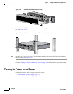
Step 1 Power down your router. (See the “Powering Down the Router” section on page 3-2.)
Step 2 Attach an ESD-preventive wrist strap to your wrist, and to the router or to a bare metal surface. (See the
“Preventing Electrostatic Discharge” section on page 2-4.)
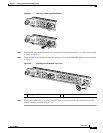
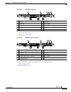
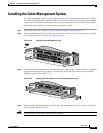
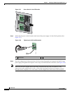
Figure 3-19 Attaching Cable-Management Tray
Step 3
Attach the cable-management tray to the router using four of the 3.5-mm x 6-mm screws that are shipped
with the router. Secure the tray with two screws on each side of the router chassis using a Number 1
Phillips screwdriver. (See Figure 3-19.)
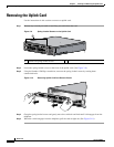
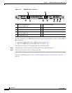
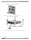
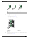
Figure 3-20 Managing Router Cables with the Cable-Management Tray
Step 4 Separate cables and lead them out the sides of the cable-management tray. Use a cable tie to keep the
cables together. (See Figure 3-20.)
Caution To avoid damage to the cables, avoid excessive bending.
AC OK
DC OK
OTF
AC OK
DC OK
OTF
INPUT 100-200- 50/60Hz 2-5A
DON NOT REMOVE
OR INSERT CABLES
WITH THE POWER ON
CARD FAIL
CARD FAIL
LINK/ACTIVE (G)
100 MBPS
POWER
RESET
CONSOLE
AUX
OVERTEMP
AC
TIVE
CARD FAIL
SYSTEM STAUS
POWER
C
A
R
R
IER
R
X P
K
T
W
R
AP
P
AS
S
T
H
R
U
66296
AC OK
DC OK
OTF
AC OK
DC OK
OTF
INPUT 100-200- 50/60Hz 2-5A
DON NOT REMOVE
OR INSERT CABLES
WITH THE POW
ER ON
CARD FAIL
CARD FAIL
LINK/ACTIVE (G)
100 MBPS
POWER
RESET
CONSOLE
AUX
OVERTEMP
ACTIVE
CARD FAIL
SYSTEM STAUS
POWER
CARRIER
RX PKT
WRAP
PASS THRU
57749