


3-22
Book Title
78-13113-06 B0
Chapter 3 Installing and Removing the Uplink Cards
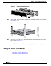
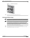
Turning On Power to the Router
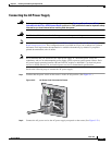
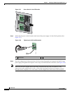
Note Leave a small service loop in the ground lead to ensure that the ground lead is the last lead to
disconnect from the power supply if a great deal of strain is placed on the DC-input leads. It is
important that the ground power lead is the last to disconnect from the power supply terminal.
Note Allow sufficient slack in the power cable leads for strain relief. The power cable leads should be
adequately secured to prevent the power supply terminal connections from being subjected to strain.
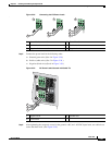
Step 7 After wiring the DC power supply, remove the tape from the circuit breaker switch handle and turn on
power by moving the handle of the circuit breaker to the on position.
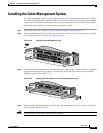
If you are installing the cable-management system, go to the “Installing the Cable-Management System”
section on page 3-15. If not, install the cables, and then power up the router.