


3-4
Book Title
78-13113-06 B0
Chapter 3 Installing and Removing the Uplink Cards
Removing the Cable-Management System
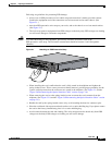
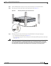
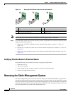
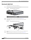
Figure 3-3 Removing the DC Power Leads from the Terminal Block
Note The DC site power source must be disconnected to ensure proper safety is maintained.
Step 5 Loosen the three locking screws for the negative, positive, and ground screw connectors on the DC power
supply terminal block as follows:
a. Remove the –48 VDC lead (black) from the terminal block negative connector (–). (See 1 in
Figure 3-3.)
b. Remove the +48 VDC lead (white wire) from the terminal block positive connector (+). (See 2 in
Figure 3-3.)
c. Remove the safety ground lead (green wire) from the terminal block ground connector. (See 3 in
Figure 3-3.)
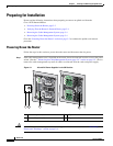
Verifying That the Router Is Powered Down
Check the following to ensure that your router is properly powered down:
• LED lights are off.
• Fans are not running.
• Power switch indicates the power supply is turned to the off position (O).
• Power is disconnected at the source.
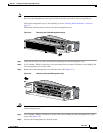
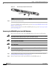
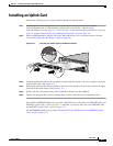
Removing the Cable-Management System
The cable-management system, located on the front of the Cisco 10720 Internet Router, organizes the
interface cables that lead into and away from the router. To keep the cables free of sharp bends, extend
the cables from the center out both sides of the cable-management tray. Excessive bending of an interface
cable can degrade performance and possibly harm the cable. The cable-management system consists of
the cable-management tray and the cable-management cover.
1 Negative lead disconnected 4 Ground lead
2 Positive lead disconnected 5 Positive lead
3 Ground lead disconnected 6 Negative lead
122050
3
2
4
4
5
1
4
5
6