


C-1
Cisco Aironet 1200 Series Access Point Hardware Installation Guide
OL-8370-04
APPENDIX
C
Access Point Specifications
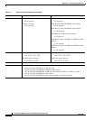
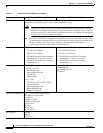
This appendix provides technical specifications for the 1200 series access point (see Table C-1).
Note The lightweight access points (models: AIR-LAP1231G and AIR-LAP1232AG) do not support the
802.11b radio or the RM20A radio module.
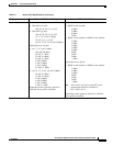
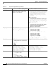
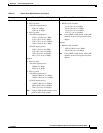
Table C-1 Access Point Specifications
Category Access Point with 802.11b or 802.11g Radio Access Point with 802.11a Radio Module
Size 6.56 in. W x 7.23 in. D x 1.66 in. H
16.67 cm W x 18.36 cm D x 4.22 cm H
With the antenna in the patch position (RM20A or
RM
21A):
6.56 in. W x 8.04 in. D x 2.21 in. H
16.67 cm W x 20.42 cm D x 5.61 H
With the RM22A radio module:
6.56 in. W x 8.76 in. D x 1.66 in. H
16.67 cm W x 22.25 cm D x 4.22 cm H
Status Indicators Three indicators on the top panel: Ethernet traffic, status, and radio traffic.
Connectors Base unit:
Back panel (left to right): Left RP-TNC antenna connector; power connector (for plug-in AC
po
wer module); RJ-45 connector for 10BASE-T or 100BASE-T Ethernet connections; upside
down RJ-45 connector for serial connections; right RP-TNC antenna connector.
Front Panel: Card Bus connector used for an 802.11a radio module.
RM22A radio module:
Left and right RP-TNC antenna connectors
Input Voltage 48 VDC nominal. Operational up to 60 VDC. Voltage higher than 60 VDC can damage the unit.