


2-5
Cisco Aironet 1200 Series Access Point Hardware Installation Guide
OL-8370-04
Chapter 2 Installing the Access Point
Before Beginning the Installation
Before Beginning the Installation
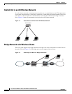
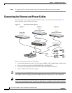
Before you begin the installation process, please refer to Figure 2-1, Figure 2-2, and Figure 2-3 to
become familiar with the access point’s layout, connectors, and 5-GHz module location.
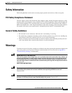
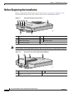
Figure 2-1 Access Point Layout and Connectors
Note Do not connect Cisco 5-GHz antennas with blue labels or blue dots to the 2.4-GHz antenna connectors.
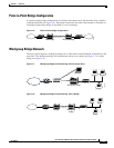
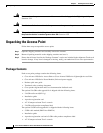
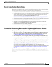
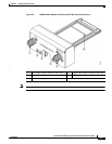
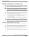
Figure 2-2 Access Point with 5-GHz Radio Module (RM21A)
1 2.4-GHz antenna connectors 5 Mode button
2 48-VDC power port 6 Status LEDs
3 Ethernet port (RJ-45) 7 Mounting bracket
4 Console port (RJ-45)
1 2 3 4 6
7 1
5
65847
1 Module mounting screws 3 Access point
2 Integrated antenna in patch position
(RM21A radio module)
74631
1 1 2 3