


1-5
Cisco Aironet 1200 Series Access Point Hardware Installation Guide
OL-8370-04
Chapter 1 Overview
Hardware Features
All 5-GHz radio modules incorporate an Unlicensed National Information Infrastructure (UNII) radio
transceiver operating in the UNII 5-GHz frequency bands. The RM21A radio modules contains dual
integrated omnidirectional antennas and directional antennas for diversity operation. For autonomous
access points, the 802.11g radio is called Radio0 and the 802.11a radio is called Radio1.
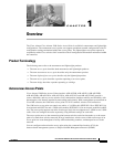
LEDs
The three LEDs on the top of the access point report Ethernet activity, association status, and radio
activity.
• The Ethernet LED signals Ethernet traffic on the wired LAN, or Ethernet infrastructure. This LED
is normally green when an Ethernet cable is connected and blinks green when a packet is received
or transmitted over the Ethernet infrastructure. The LED is off when the Ethernet cable is not
connected.
• The status LED signals operational status. Green indicates that the access point is associated with
at least one wireless client. Blinking green indicates that the access point is operating normally but
is not associated with any wireless devices.
• The radio LED signals wireless traffic over the radio interface. The light is normally off, but it blinks
green whenever a packet is received or transmitted over the access point radio.
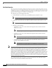
Figure 1-1 sh
ows the three status LEDs.
Figure 1-1 Access Point LEDs
Ethernet Port
The auto-sensing Ethernet port accepts an RJ-45 connector, linking the access point to your 10BASE-T
or 100BASE-T Ethernet LAN. The access point can receive power through the Ethernet cable from a
power injector, switch, or power patch panel. The Ethernet MAC address is printed on the label on the
back of the access point.
Radio
Status
Ethernet
86704