


E-2
Cisco Aironet 1200 Series Access Point Hardware Installation Guide
OL-8370-04
Appendix E Console Cable Pinouts
Overview
Overview
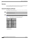
The access point requires a special serial cable that connects the access point serial console port (RJ-45
connector) to your PC’s COM port (DB-9 connector). This cable can be purchased from Cisco (part
number AIR-CONCAB1200) or can be built using the pinouts in this appendix.
Console Port Signals and Pinouts
Use the console RJ-45 to DB-9 serial cable to connect the access point’s console port to the COM port
of your PC running a terminal emulation program.
Note Both the Ethernet and console ports use RJ-45 connectors. Be careful to avoid accidently connecting the
serial cable to the Ethernet port connector.
Note When your configuration changes are completed, you must remove the serial cable from the access point.
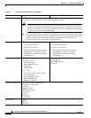
Table E-1 lists th
e signals and pinouts for the console RJ-45 to DB-9 serial cable.
Table E-1 Signals and Pinouts for a Console RJ-45 to DB-9 Serial Cable
Console Port PC COM Port
RJ-45 DB-9
Pins Signals
1, 2, 3, 4
1. NC indicates not connected.
2. TXD indicates transmit data.
3. GND indicates ground.
4. RXD indicates receive data.
Pins Signals
1, 2, 3, 4
1 NC – –
2 NC – –
3 TXD 2 RXD
4 GND 5 GND
5 GND 5 GND
6 RXD 3 TXD
7 NC – –
8 NC – –