


1-5
Hardware Installation Guide for Cisco Media Experience Engine 3000
OL-17000-01
Chapter 1 Introducing the Cisco MXE 3000
Hardware Features
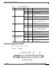
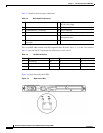
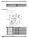
Table 1-4 describes the back panel LEDs and their functions.
Ta b l e 1-4 Back Panel LEDs
LED Color State Description
1 NIC/iLO 2 activity Green On Activity exists.
Green Flashing
- Off No activity exists.
2 NIC/iLO 2 link Green On Link exists.
- Off No link exists.
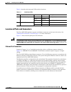
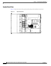
Location of Ports and Connectors
The Cisco MXE 3000 appliance supports two Ethernet connectors on the back of the device. See
“Ethernet Port Connectors” section on page 1-5, for more information.
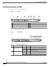
Figure 1-3 shows the back panel ports and connectors.
Warning
To avoid electric shock, do not connect safety extra-low voltage (SELV) circuits to telephone-network
voltage (TNV) circuits. LAN ports contain SELV circuits, and WAN ports contain TNV circuits. Some
LAN and WAN ports both use RJ-45 connectors. Use caution when connecting cables.
Statement 1021
Ethernet Port Connectors
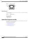
Connect a Category 3, 4, or 5 unshielded twisted-pair cable to an Ethernet connector (shown in
Figure 1-5). 100BASE-TX and 1000BASE-T Fast Ethernet standards require Category 5 or higher
cabling.
The Cisco MXE 3000 has three Ethernet connectors. Two of the Ethernet connectors are attached to the
Ethernet controllers and the third connector is the systems-management Ethernet connector, which is not
supported by the Cisco
MXE 3000 software.
The Ethernet controllers are integrated on the system board. They provide an interface for connecting to
a 10-Mbps, 100-Mbps, or 1-Gbps network and provide full-duplex (FDX) capability, which enables
simultaneous transmission and reception of data on the network. If the Ethernet ports in the appliance
support auto negotiation, the controllers detect the data-transfer rate (10BASE-T, 100BASE-TX, or
1000BASE-T) and duplex mode (full duplex or half duplex) of the network and automatically operate at
that rate and mode. You do not have to set any jumpers or configure the controllers.
If a problem occurs with the primary Ethernet connection, all Ethernet traffic associated with this
primary connection is automatically switched to the redundant Ethernet connection. If the applicable
device drivers are installed, switching occurs without data loss and without user intervention.