


1-7
Hardware Installation Guide for Cisco Media Experience Engine 3000
OL-17000-01
Chapter 1 Introducing the Cisco MXE 3000
System Board Components and LEDs
System Board Components
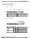
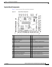
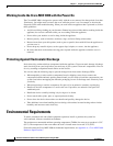
Figure 1-7 shows the layout of the system board components.
Figure 1-7 System Board Components
1 2 3 4 6 7 8
30
31
32
33
34
35
36
37
29 2 27 26 25 24 23 22 21 20 19 18
5
9
10
11
12
13
14
15
16
17
189141
1 DIMM slot 1 (bank A) 20 SATA connector 4 (hard drive)
2 DIMM slot 2 (bank B) 21 SATA connector 6 (optical drive)*
3 DIMM slot 3 (bank C) 22 Reserved
4 DIMM slot 4 (bank D) 23 Reserved
5 Processor socket 24 SATA connector 5 (optical drive)*
6 Reserved 25 Internal USB option connector
7 System power connector 26 Reserved
8 Processor power connector 27 SATA connector 3 (hard drive)
9 Fan 1 connector 28 SATA connector 1 (hard drive)
10 Fan 2 connector 29 Parallel option connector
11 Fan 3 connector 30 Serial option connector
12 Front USB cable connector 31 Reserved
13 SATA connector 2 (hard drive) 32 PCI Express expansion slot 4
14 Front panel LED connector 33 PCI Express expansion slot 5**
15 NMI jumper 34 R served
16 Reserved 35 Reserved