


1-9
Hardware Installation Guide for Cisco Media Experience Engine 3000
OL-17000-01
Chapter 1 Introducing the Cisco MXE 3000
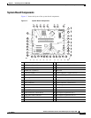
System Board Components and LEDs
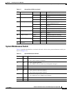
System Maintenance Switch
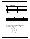
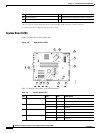
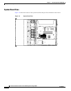
Table 1-6 describes the functions associated with each switch on the system maintenance switch (see
Item 17 of Figure 1-7).
Ta b l e 1-6 System Maintenance Switch
Position Default Function
S1 Off • Off = iLO 2 security is enabled
• On = iLO 2 security is disabled
S2 Off • Off = Normal operation
• On = RBSU will not commit any configuration changes*
S3 Off Reserved
S4 Off Reserved
S5 Off • Off = Power-on password enabled
• On = Power-on password disabled*
S6 Off • Off = Normal operation
• On = BIOS will clear CMOS and NVRAM*
S7 Off Reserved
S8 Off Reserved
5 Fan 3 failure Amber On Fan 3 has failed or is missing.
- Off Normal.
6 PCI fan failure Amber On PCI fan has failed or is missing.
- Off Normal.
7 Overtemperature Amber On System has reached a cautionary or
critical temperature level.
- Off Normal.
8 DIMM 4 failure Amber On DIMM has failed or is missing.
- Off Normal.
9 DIMM 3 failure Amber On DIMM has failed or is missing.
- Off Normal.
10 DIMM 2 failure Amber On DIMM has failed or is missing.
- Off Normal.
11 DIMM 1 failure Amber On DIMM has failed or is missing.
- Off Normal.
12 Reserved - - -
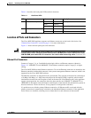
Table 1-5 System Board LEDs (continued)
LED Color State Description