


2-2
Installation and Upgrade Guide for Cisco Unified Videoconferencing 3545 MCU Release 5.1
OL-11899-01
Chapter 2 Installing the Cisco Unified Videoconferencing 3545 MCU
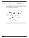
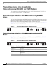
Physical Description of the Cisco Unified Videoconferencing 3545 MCU and EMP Modules
Physical Description of the Cisco Unified
Videoconferencing 3545 MCU
and EMP Modules
This section provides a physical description of the Cisco Unified Videoconferencing 3545 MCU and
Cisco Unified Videoconferencing 3545 EMP modules.
Physical Description of the Cisco Unified Videoconferencing 3545 MCU
Module
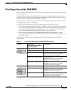
The Cisco Unified Videoconferencing 3545 MCU module has a 10/100BaseT Ethernet port on the front
panel that uses an RJ-45 connector to connect to the network. There is an asynchronous, 9-pin serial port
that you can use with a hyperterminal program to configure and monitor the module.
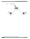
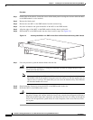
Figure 2-1 shows the front panel of the Cisco Unified Videoconferencing 3545 MCU module. Table 2-1
describes the components of the front panel.
Figure 2-1 Cisco Unified Videoconferencing 3545 MCU Front Panel
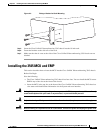
Physical Description of the Cisco Unified Videoconferencing 3545 EMP
Module
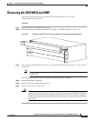
Figure 2-2 shows the front panel of the Cisco Unified Videoconferencing 3545 EMP board. Table 2-1
describes the components of the front panel.
Figure 2-2 Cisco Unified Videoconferencing 3545 EMP Front Panel
157270
10/100Base T-1
SERIAL
RST
ACTALARM
CPU-HightGK Reg
SWAP
RDY
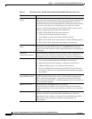
Table 2-1 Front Panel Components
Component Description
10/100 BaseT-1
connector
An RJ-45 connector that provides the primary Ethernet connection for the IP
network port.
SERIAL connector A DB-9 connector that allows you to connect a PC terminal for local
configuration.
RST button Allows you to reset the board manually.
157271
10/100Base T
SERIAL
RST
ACTALARM
CPU-HightMC
SWAP
RDY