


2-3
Installation and Upgrade Guide for Cisco Unified Videoconferencing 3545 MCU Release 5.1
OL-11899-01
Chapter 2 Installing the Cisco Unified Videoconferencing 3545 MCU
Preparing to Install the 3545 MCU
Preparing to Install the 3545 MCU
This section describes the requirements for installing the Cisco Unified Videoconferencing 3545 MCU
and the Cisco Unified Videoconferencing 3545 EMP in a Cisco Unified
Videoconferencing 3545 chassis. For more information, see the Platform Guide for Cisco IPVC 3644
Chassis.
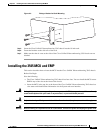
Warning
During this procedure, wear grounding wrist straps to avoid ESD damage to the card. Do not directly
touch the backplane with your hand or any metal tool, or you could shock yourself.
The requirements are as follows:
• Cisco Unified Videoconferencing 3545 chassis
• Proper clearance at the sides of the unit to allow adequate ventilation, and at least 20 cm clearance
at the back of the chassis to allow access to the boards and cable connections
• A PC with a serial port and terminal emulation software to assign the MCU and EMP an IP address
• Two dedicated IP addresses—one each for the MCU and EMP
• The IP address of the router that the MCU and EMP will use to communicate across the network
• For an H.323 environment, IP address of the H.323 gatekeeper with which you want the MCU to
register
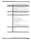
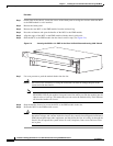
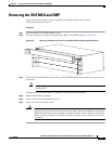
GK Reg LED (on the
Cisco Unified
Videoconferencing 354
5MCU)
MC LED (on the
Cisco Unified
Videoconferencing 354
5EMP)
Lights green when the MCU is registered with a gatekeeper. Lights green
when the EMP is registered with the MCU.
CPU High LED Lights green when more than 50% of the MCU/EMP resources are in use.
ACT LED Lights green to indicate that there is at least one currently active conference
on the MCU/EMP.
ALARM LED Lights green to indicate that an error has occurred and the MCU/EMP
requires resetting.
10/100 BaseT-1 LEDs The top part of the 10/100 BaseT-1 connector contains two LED indicators.
The left-hand LED lights green when the local IP network link is active. The
right-hand LED lights green if the connection speed is 100 Mbps, and is off
when the connection speed is 10 Mbps.
SWAP RDY LED Hot Swap indication. Lights blue when the latches of a board are unlocked
and it is safe to remove the board from the chassis. Goes off when the board
is completely detached.
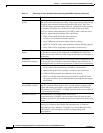
Table 2-1 Front Panel Components (continued)
Component Description