


2-7
Installation and Upgrade Guide for Cisco Unified Videoconferencing 3545 MCU Release 5.1
OL-11899-01
Chapter 2 Installing the Cisco Unified Videoconferencing 3545 MCU
Removing the 3545 MCU and EMP
Removing the 3545 MCU and EMP
This section describes how to remove the MCU or the EMP from the Cisco Unified
Videoconferencing 3545 chassis.
Procedure
Step 1 Loosen the MCU or the EMP module screws.
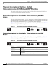
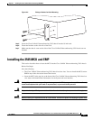
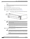
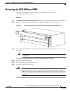
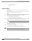
Step 2 Press the red buttons and open the handles of the MCU or the EMP module (see Figure 2-5).
Figure 2-5 Removing a Module from the Cisco Unified Videoconferencing 3545 Chassis
Step 3 Wait for the blue SWAP RDY LED to light up. The SWAP RDY LED indicates that it is safe to remove
the module.
Note It may take up to one minute for the LED to light up while the Windows operating system is
shutting down.
The light goes out when the board is completely detached from the backplane.
Step 4 Remove the module completely.
Step 5 Insert a blank cover panel provided by Cisco.
Step 6 Secure the blank cover panel screws.
Caution Blank faceplates and cover panels serve three important functions: they prevent exposure to
hazardous voltages and currents inside the chassis; they contain electromagnetic interference
(EMI) that might disrupt other equipment; and they direct the flow of cooling air through the
chassis. Do not operate the system unless all cards, faceplates, front covers, and rear covers
are in place.
157279