


C-3
Catalyst 3750-X and 3560-X Switch Hardware Installation Guide
OL-19593-01
Appendix C Configuring the Switch with the CLI-Based Setup Program
Accessing the CLI
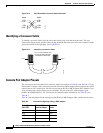
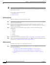
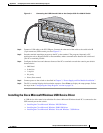
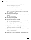
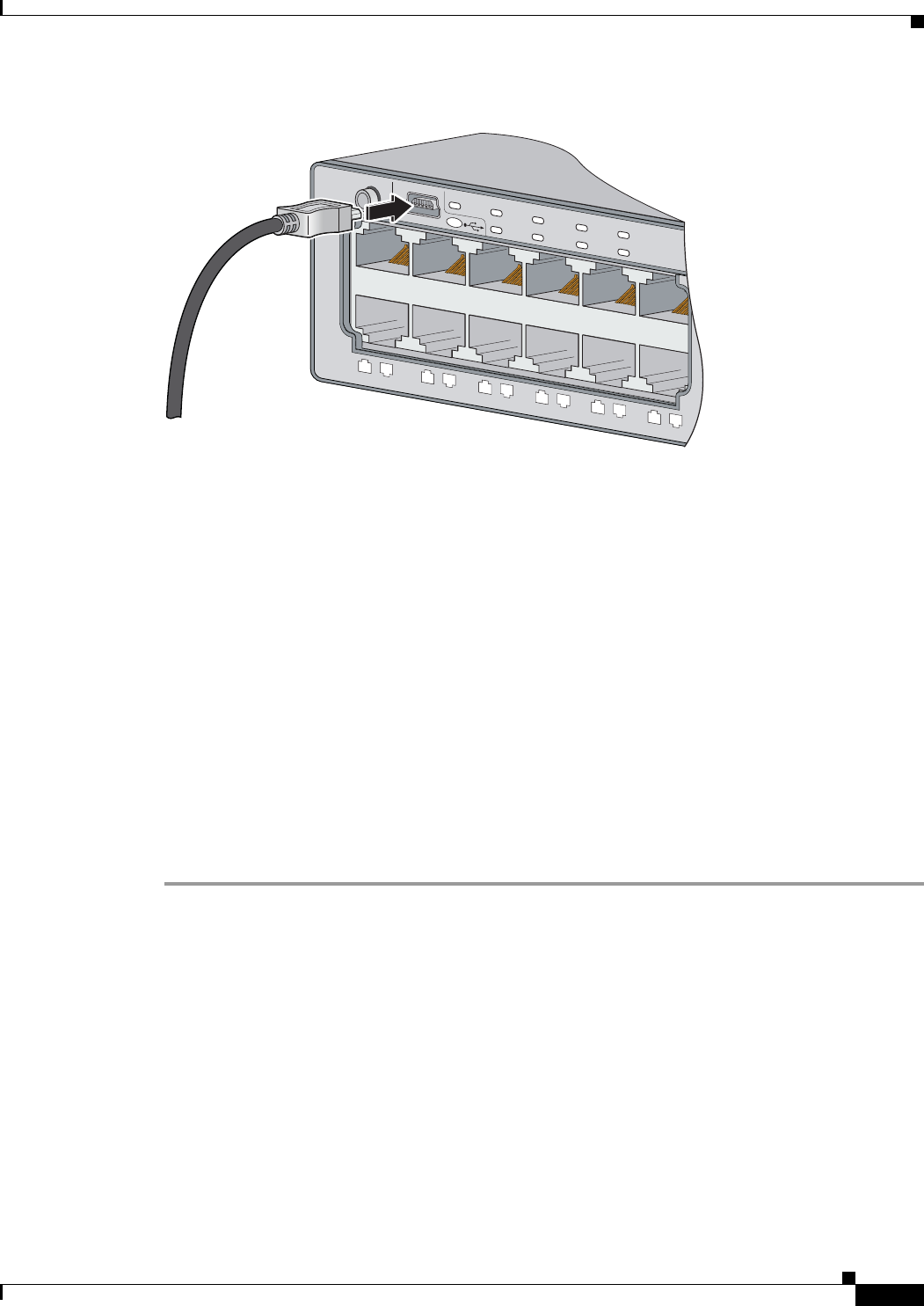
Figure C-1 Connecting the USB Console Cable to the Catalyst 3750-X or 3560-X Switch
Step 2 Connect a USB cable to the PC USB port. Connect the other end of the cable to the switch mini-B
(5-pin-connector) USB console port. See
Figure C-1.
Step 3 Start the terminal-emulation program on the PC or the terminal. The program, frequently a PC
application such as HyperTerminal or ProcommPlus, makes communication between the switch and
your PC or terminal possible.
Step 4 Configure the baud rate and character format of the PC or terminal to match the console port default
characteristics:
• 9600 baud
• 8 data bits
• 1 stop bit
• No parity
• None (flow control)
Step 5 Connect power to the switch as described in Chapter 3, “Power Supply and Fan Module Installation.”.
Step 6 The PC or terminal displays the bootloader sequence. Press Enter to display the setup prompt. Follow
the steps in the
“Configuring the Setup Program” section on page C-6.
Installing the Cisco Microsoft Windows USB Device Driver
A USB device driver must be installed the first time a Microsoft Windows-based PC is connected to the
USB console port on the switch.
• Installing the Cisco Microsoft Windows XP USB Driver
• Installing the Cisco Microsoft Windows 2000 USB Driver
• Installing the Cisco Microsoft Windows Vista and Windows 7 USB Driver
SYST
XPS
STAT
SPEED
DUPLX
PoE
STAC K
MAST
S-PWR
MODE
1
2
3
4
5
6
7
8
9
10
11
12
EN
CONSOLE
253406