


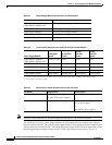

3-10
Catalyst 3750-X and 3560-X Switch Hardware Installation Guide
OL-19593-01
Chapter 3 Power Supply and Fan Module Installation
Installing a DC Power Supply
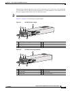
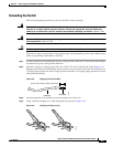
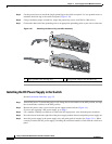
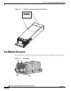
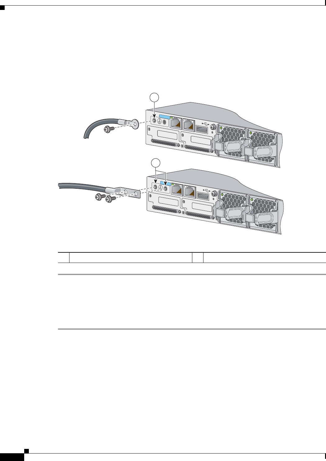
Step 5 Use the ground screw to attach the single-ground lug to the switch rear panel. Use two ground screws to
attach the dual-hole lug to the switch rear panel (
Figure 3-10).
Step 6 Using a ratcheting torque screwdriver, torque the ground-lug screws to 60 lbf-in. (960 ozf-in.).
Step 7 Connect the other end of the grounding wire to an appropriate grounding point at your site or to the rack.
Figure 3-10 Attaching the Ground Lug and Wire Assembly
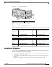
Installing the DC Power Supply in the Switch
See the Installation Guidelines, page 3-5.
Step 1 Turn off DC power. To ensure that power is off, change the circuit breakers to the OFF position, and tape
the circuit-breaker switches in the OFF position.
Step 2 Remove the plastic safety cover from the power supply terminal blocks (Figure 3-4).
If you are not replacing a DC power supply, go to Step 5.
Step 3 Use a number-2 Phillips screwdriver to remove the DC-input power wires from the power terminals.
Step 4 Press the release latch at the right side of the power supply module inward, and pull the power supply out.
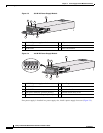
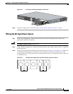
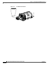
Step 5 Insert the power supply in the power-supply slot, and gently push it into the slot (Figure 3-11). When
correctly installed, the DC power supply (excluding the extraction handle) is flush with the switch rear
panel.
1 Single-ground screw and lug ring 2 Dual-ground adaptor and dual-hole lug
RESET
CONSOLE
STACK 1
STACK 2
AUX
RESET
CONSOLE
STACK 1
STACK 2
AUX
253161
2
1