


2-20
Catalyst 3750-X and 3560-X Switch Hardware Installation Guide
OL-19593-01
Chapter 2 Switch Installation
Installing the Switch
When you complete the switch installation, see the “After Installing the Switch” section on page 2-21
for more information about switch configuration.
Table- or Shelf-Mounting
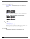
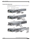
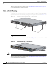
To install the switch on a table or shelf, locate the adhesive strip with the rubber feet in the mounting-kit
envelope. Attach the four rubber feet to the recessed areas on the bottom of the chassis (See
Figure 2-20).
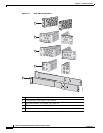
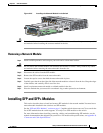
Figure 2-20 Attaching the Adhesive Pads for Table- or Shelf-Mounting
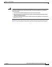
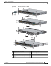
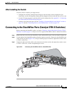
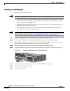
You can also attach the brackets for a 19-inch rack as shown in Figure 2-21 to secure the switch to a shelf
or table.
Figure 2-21 Using Brackets for Table- or Shelf-Mounting
Caution Do not wall-mount the switch.
When you complete the switch installation, see the “After Installing the Switch” section on page 2-21
for more information switch configuration.
1 Adhesive pads
RESET
CONSOLE
STACK 1
STACK 2
AUX
S-PWR
XPS
S-PWR
253209
1
1
AC OK
C3KX-PWR-715WAC
PS OK
AC OK
C3KX-PWR-715WAC
PS OK
253403
Catalyst 3750-X PoE+48
SYST
XPS
STAT
SPEED
DUPLX
EN
PoE
STACK
MAST
S-PWR
MODE
CONSOLE
C3KX-NM-10G
NETWORK
MODULE
G1
G2/TE1
G3
G4/TE2
1
2
3
4
5
6
7
8
9
10
11
12
13
14
15
16
17
18
19
20
21
22
23
24
25
26
27
28
29
30
31
32
33
34
35
36
37
38
39
40
41
42
43
44
45
46
47
48