


1-20
Catalyst 3750-X and 3560-X Switch Hardware Installation Guide
OL-19593-01
Chapter 1 Product Overview
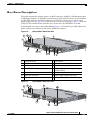
Rear Panel Description
The nine ports on the XPS-2200 provide the power and management signals to the Catalyst 3750-X and
3560-X switches. Other switch models do not support this management communication. The XPS-2200
communicates with each switch through the 12-pin cable. All connected switches can simultaneously
communicate with the XPS-2200. You can configure these XPS-2200 features through the switch
software:
• Enable XPS active or standby mode for each connected switch
• Configure switch priority for XPS support
• List the connected switches and power supply module sizes
• Report when a switch is powered by the XPS
• Report the XPS power supply module status
• Read and monitor backup, failure, and exception history
See the switch software configuration guide on Cisco.com:
http://www.cisco.com/en/US/products/ps10745/products_installation_and_
configuration_guides_list.html
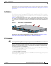
StackPower Connector (Catalyst 3750-X Switches)
The Catalyst 3750-X switches have a StackPower connector for use with Cisco StackPower cables to
configure a switch power stack that includes up to four switches. By adding an XPS-2200 expandable
power system, you can configure a power stack that comprises up to nine switches. A switch power stack
can be configured in redundant or power-sharing mode.
You can order these StackPower cables from your Cisco sales representative:
• CAB-SPWR-30CM (0.3-meter cable)
• CAB-SPWR-150CM (1.5-meter cable)
For details about connecting StackPower cables and StackPower guidelines, see the “Planning a
StackPower Stack (Catalyst 3750-X Switches)” section on page 2-8.
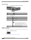
Management Ports
Ethernet Management Port
You can connect the switch to a host such as a Windows workstation or a terminal server through the
10/100
Ethernet management port or one of the console ports (see Figure 1-5 and Figure 1-6). The
10/100 Ethernet management port connection uses a RJ-45 crossover or straight-through cable. The
RJ-45 console port connection uses the supplied RJ-45-to-DB-9 female cable. The USB console port
uses a USB type-A-to-USB 5-pin mini-Type B cable.
Table 1-19 shows the Ethernet management port LED colors and their meanings.
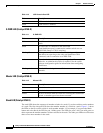
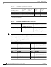
Ta b l e 1-19 RJ-45 Console Port LED
Color Description
Green Active link to PC