


CHAPTER
3-1
Catalyst 3750-X and 3560-X Switch Hardware Installation Guide
OL-19593-01
3
Power Supply and Fan Module Installation
• Power Supply Module Overview, page 3-1
• Installation Guidelines, page 3-5
• Installing an AC Power Supply, page 3-6
• Installing a DC Power Supply, page 3-7
• Finding the Power Supply Module Serial Number, page 3-12
• Fan Module Overview, page 3-14
• Installing a Fan Module, page 3-15
• Finding the Fan Module Serial Number, page 3-15
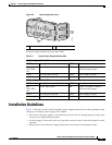
Power Supply Module Overview
The switch operates with either one or two active power supply modules or with power supplied by an
expandable power supply, XPS-2200. A Catalyst 3750-X switch that is part of a StackPower stack
operates with power supplied by other stack switches.
You can use two AC modules, two DC modules, one AC and one DC module, or one module and a blank
cover.
All power supply modules have internal fans. All switches ship with a blank cover in the second power
supply slot.
The XPS-2200 operates in two modes:
• In StackPower mode, it supplies power to the switches in the power stack (only Catalyst 3750-X
switches with IP Base image).
• In expandable power supply mode, it supplies power to a switch when the switch power supply is
removed or fails. When you install or replace a power supply module, the switch software polls the
device. After polling, the power supply module provides power to the switch, and the XPS-2200 is
available to power other devices.
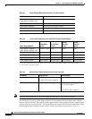
Table 3-1 describes the supported internal power supply modules.