


1-14
Catalyst 3750-X and 3560-X Switch Hardware Installation Guide
OL-19593-01
Chapter 1 Product Overview
Front Panel Description
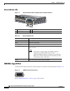
Network Module LEDs
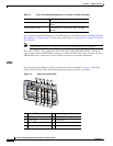
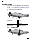
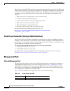
Figure 1-4 Network Module LEDs (10-Gigabit Network Module Shown)
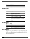
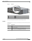
USB Mini-Type B Port
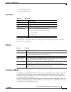
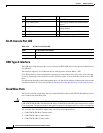
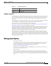
A USB 5-pin mini-Type B connector on the front panel is available for switch management (Figure 1-5).
Figure 1-5 USB Mini-Type B Console Port
See the “Management Ports” section on page 1-20 for details.
1 G1 LED 3 G3 LED
2 G2/TE1 LED 4 G4/TE2 LED
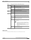
Ta b l e 1-14 Network Module LEDs
Color Network Module Link Status
Off Link is off.
Green Link is on, no activity.
Blinking green Activity on a link, no faults.
Blinking amber Link is off due to a fault or because it has exceeded a limit set in the
switch software.
Caution Link faults are caused when noncompliant cabling is
connected to an SFP or SFP+ port. Use only
standard-compliant cabling to connect to Cisco SFP and
SFP+ ports. You must remove from the network any cable
or device that causes a link fault.
Amber Link for the SFP or SFP+ has been disabled.
Catalyst 3750-X PoE+48
37
38
39
40
41
42
43
44
45
46
47
48
C3KX-NM-10G
NETWORK
MODULE
G1
G2/TE1
G3
G4/TE2
253212
1
2
3
4
253163