


2-9
Catalyst 3750-X and 3560-X Switch Hardware Installation Guide
OL-19593-01
Chapter 2 Switch Installation
StackPower Cabling Configurations
For general concepts and management procedures for switch power stacks, see the switch software
configuration guide on Cisco.com.
Before connecting the switches in a power stack, keep in mind these guidelines:
• A switch power stack can include a maximum of four switches in a ring topology and nine switches
in a star topology with the XPS-2200.
• Size of the switch and any optional power supply module. The 1100-W power-supply module is
1.5
inches longer than the other modules, and with the attached cable retention clip, it extends
3
inches from the switch chassis. Stacking switches with the same power-supply modules together
makes it easier to cable the switches. For switch dimensions, see
Appendix A, “Technical
Specifications.”
• Length of cable. Depending on the configurations that you have, you might need different-sized
cables. If you do not specify the length of the StackPower cable, the 0.3 meter cable is supplied. If
you need the 1.5 meter cable, you can order it from your Cisco supplier. For cable part numbers, see
the
“StackPower Connector (Catalyst 3750-X Switches)” section on page 1-20. The “StackPower
Cabling Configurations” section on page 2-9 provides examples of recommended configurations.
• For rack-mounted switch stacks that are members of a data stack and a StackPower stack, see the
“Switch Data Stacking Guidelines” section on page 2-5.
• For rack-mounted switch stacks connected to the XPS-2200, review this recommended sequence of
events:
–
If you are using the XPS-2200, first install the XPS at the bottom of the stack. If needed, allow
one RU space between the XPS and the first switch above to provide room for cabling.
–
Connect all the 12-pin XPS cables to the XPS-2200 as needed.
–
Rack-mount the switches. If you have the optional 1100-W power-supply module, first
rack-mount the switch before installing the power-supply module.
–
Connect the XPS cable to the first switch above the XPS-2200. Connect the stack cables to the
first switch above the XPS.
–
Connect the XPS cable to the second switch above the XPS-2200. Connect the stack cables to
the second switch above the XPS.
–
Repeat until all devices are connected.
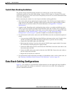
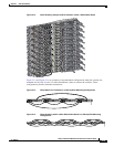
StackPower Cabling Configurations
This section describes the recommended cabling configurations for a StackPower stack. There are two
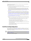
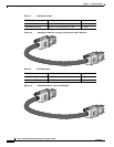
types of StackPower cables. The cable in
Figure 2-8 connects a Catalyst 3750-X switch to another
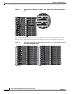
3750-X switch in a power stack or to an XPS-2200. The cable in Figure 2-9 connects a Catalyst 3750-X
or 3560-X switch to an XPS-2200.
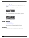
Note All cable connectors are keyed and color-coded, as are the connections on the switches (See Figure 1-6
and Figure 1-7 on page 1-15).
Both cable types are available in two lengths.