


1-5
Cisco Wide Area Virtualization Engine 594 and 694 Hardware Installation Guide
OL-24619-02
Chapter 1 Introducing the Cisco Wide Area Virtualization Engine 594 and 694
Hardware Features
Location of Ports and Connectors
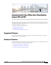
The WAVE appliance supports two Ethernet connectors and two Console ports on the front of the
appliance.
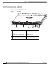
Figure 1-3 shows the back panel ports and connectors.
Warning
To avoid electric shock, do not connect safety extra-low voltage (SELV) circuits to telephone-network
voltage (TNV) circuits. LAN ports contain SELV circuits, and WAN ports contain TNV circuits. Some
LAN and WAN ports both use RJ-45 connectors. Use caution when connecting cables.
Statement 1021
This section contains the following topics:
• Ethernet Port Connectors
• Console Port Connector
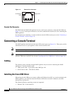
Ethernet Port Connectors
Connect a Category 3, 4, or 5 unshielded twisted-pair cable to an Ethernet connector. 100BASE-TX and
1000BASE-T Fast Ethernet standards require Category 5 or higher cabling.
The WAVE-594 and WAVE-694 appliance has two Ethernet connectors that are attached to the Ethernet
controllers (see Figure 1-5). The Ethernet controllers are integrated on the system board. They provide
an interface for connecting to a 10-Mbps, 100-Mbps, or 1-Gbps network and provide full-duplex (FDX)
capability, which enables simultaneous transmission and reception of data on the network. If the
Ethernet ports in the server support auto negotiation, the controllers detect the data-transfer rate
(10BASE-T, 100BASE-TX, or 1000BASE-T) and duplex mode (full duplex or half duplex) of the
network and automatically operate at that rate and mode. You do not have to set any jumpers or configure
the controllers.
Note There is a third RJ45 connector on the front of the appliance (see Figure 1-1). This is a console port. Do
not connect this port to your network.
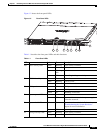
3 - 8 Fan status Orange On Alarm.
Orange Blinking Alarm. Fan speed too low.
— Off Normal state.
Table 1-2 Back Panel LEDs (continued)
LED Color State Description