


4-4
Cisco Wide Area Virtualization Engine 594 and 694 Hardware Installation Guide
OL-24619-02
Chapter 4 Installing Hardware Options for the WAVE-594 and WAVE-694
Replacing a Fan
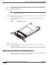
Step 4 Within one minute, insert the new drive into the same slot by aligning the replacement drive assembly
with guide rails in the bay and sliding the drive assembly into the bay until it stops. Make sure that the
drive is properly seated in the bay.
Step 5 Close the drive handle.
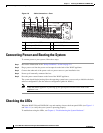
Step 6 Check the hard disk drive status LED after the system has booted to verify that the hard disk drive is
operating correctly. If the amber hard disk drive status LED for a drive is lit continuously, that drive is
faulty and must be replaced. If the green hard disk drive activity LED is flashing, the drive is being
accessed.
Step 7 Wait 1 minute and then verify that the replaced disk drive is in the Rebuilding state by using the show
disks details command in EXEC mode.
Note The system automatically starts the rebuild operation when it detects the removal and reinsertion
of a drive that is part of the logical RAID drive.
Step 8 Wait until the rebuild operation is complete. A disk rebuild operation may take several hours. You can
check if the rebuild operation is complete by using the show disk details command in EXEC mode. The
physical drive state will be Online and the RAID logical drive state will be Okay after the rebuild
operation is completed.
Step 9 Use the show disk tech command in EXEC mode to verify that the firmware and BIOS information is
correct for both hard drives.
If you have multiple disk failures and your RAID-1 logical status is Offline, you must recreate the
RAID-1 array. For more information on disk removal and replacement procedures, see the Cisco Wide
Area Application Services Configuration Guide chapter named “Maintaining Your WAAS System.”
Replacing a Fan
The WAVE appliance supports six fan assemblies that are hot-swappable.
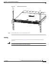
Fan assemblies can only be inserted in one orientation.
Note Fan assemblies must be inserted and can only function with the surface marked “TOP” facing up.
Caution To maintain proper system cooling, do not operate the appliance for more than 1 minute without a fan
installed in each bay.
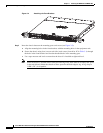
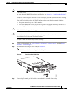
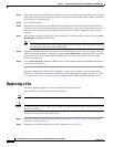
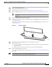
To replace a fan assembly, follow these steps:
Step 1 Review the information in the “Safety Warnings and Cautions” section on page 2-1 and the “Safety
Guidelines” section on page 2-2.
Step 2 Disengage the fan latch and pull the fan out by the handle (see Figure 4-3).