


5-7
Cisco Wide Area Virtualization Engine 594 and 694 Hardware Installation Guide
OL-24619-02
Chapter 5 WAVE Interface Modules
Ports and LED Indicators
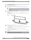
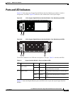
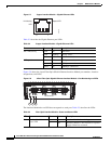
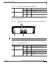
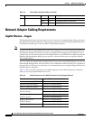
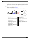
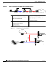
Figure 5-9 shows the 2-port Fiber Optic 10 Gibabit Ethernet SFP+ Interface Module port numbers,
interface designations, and LEDs.
Figure 5-9 2-Port Fiber Optic 10 Gigabit Ethernet SFP+ Interface Module—Port Numbering and
LEDs
Note The 2-Port Fiber Optic 10 Gigabit Ethernet SFP+ Interface Module does not support mechanical bypass.
The Interface Module has an LED that corresponds to each port. Table 5-4 describes the LEDs.
2 Activity Green On Link exists.
Green Blinking Transmitting.
— Off No link detected.
3 Bypass status Green Normal Indicates the inline port pair is in interception
mode.
Amber Bypass Indicates the inline port pair is in bypass
mode.
Table 5-3 Fiber Optic Interface Module—Power and Status LEDs
246551
AS AS
10GE 0
10GE 1
2 Port 10GE SFP+
1 4
2 3
Table 5-4 Inline Network Adapter LEDs
LED Name Color State Description
1 Interface Module
Power LED
Green On Interface Module is receiving power.
— Off Interface Module is not installed or a power
supply failure has occurred.
2 Activity — Off No link is detected.
Green On Link is detected.
Green Blinking Transmitting.
Yellow On Interface Module is administratively shut
down.