


5-4
Cisco Wide Area Virtualization Engine 594 and 694 Hardware Installation Guide
OL-24619-02
Chapter 5 WAVE Interface Modules
Interface Module Descriptions
Inline Interface
When you configure the WAVE appliance for inline interception mode, you can set attributes to control
which interfaces are to be used over which VLANs. By default, the module operates on all inline-capable
interfaces and VLANs. You can configure the inline redirection feature using the WAAS CLI or the
WAAS Central Manager GUI.
Note Throughout this section, we refer to a WAVE appliance configured for inline interception mode as a
WAVE inline appliance.
The WAAS software defines two interface types: A group interface that represents an inline pair
grouping and a port interface that represents the individual port. These interfaces are referred to as
inlineGroup and inlinePort.
InlineGroup interfaces are numbered using the format slot/group. The slot number is the slot in which
the adapter is inserted. Since there is only one slot, the slot number is always 1.
The group number starts from 0 and can go up to 4 on 8-port Interface Modules. For 4-port Interface
Modules, the groups are numbered 0 and 1. Groups are numbered from left to right.
InlinePort interfaces are numbered slot/group/lan or slot/group/wan. The last attribute is the LAN or
WAN designator.
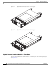
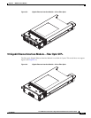
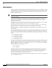
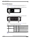
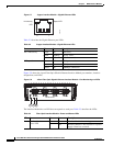
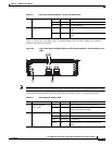
For copper Interface Modules, the top row consists of WAN ports and the bottom row consists of LAN
ports. For fiber Interface Modules, the ports are designated as WAN and LAN form left to right. For
example, the four ports on the 4-port fiber Interface Module are designated as “W0 L0 W1 L1” in inline
mode:
• W0—InlineGroup 1/0/WAN
• L0—InlineGroup 1/0/LAN
• W1—InlineGroup 1/1/WAN
• L1—InlineGroup 1/1/LAN
The inline network adapter also includes an onboard programmable watch dog timer (WDT) controller
that allows you to set the time to wait after a failure event, such as a power outage or a kernel crash,
before the unit begins to operate in mechanical bypass mode. This can be configured using the inline
failover timeout global configuration command:
(config)# inline failover timeout ?
<1-1> 1 second
<25-25> 25 seconds
<5-5> 5 seconds
In mechanical bypass mode, the traffic is bridged between the LAN and WAN ports of each group.
Mechanical bypass mode prevents the WAVE appliance from becoming a single point of failure and
allows traffic to continue to flow between the router and the client while it passes through an
unresponsive WAVE appliance without being processed.
For more information about configuring the inline network adapter, see the Cisco Wide Area Application
Services Configuration Guide.