


1-14
Cisco 7200 VXR Installation and Configuration Guide
OL-5013-08
Chapter 1 Cisco 7200 VXR Product Overview
Field-Replaceable Units
• Booting and reloading images
• Managing port adapters (recognition and initialization during online insertion and removal)
The following figures and memory tables provide information about your NPE or NSE:
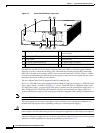
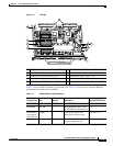
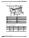
• NPE-G2 isrepresented by Figure 1-5. Table 1-3 listsNPE-G2 memory specifications, and Table 1-3
lists memory configurations.
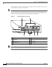
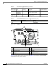
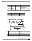
• NPE-G1 isrepresented by Figure 1-6. Table 1-4 listsNPE-G1 memory specifications, and Table 1-5
lists memory configurations.
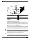
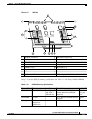
• NSE-1 is represented by Figure 1-7. Table 1-6 lists NSE-1 memory specifications, and Table 1-7
lists memory configurations.
• The NPE-400 is represented by Figure 1-8. Table 1-8 lists NPE-400 memory specifications, and
Table 1-9 lists memory configurations.
• NPE-300 is represented by Figure 1-9. Table 1-10 lists NPE-300 memory specifications, and
Table 1-11 lists memory configurations.
• NPE-225 is represented by Figure 1-10. Table 1-12 lists NPE-225 memory specifications, and
Table 1-13 lists memory configurations.
• NPE-200 is represented by Figure 1-11. Table 1-14 lists NPE-200 memory specifications, and
Table 1-15 lists memory configurations.
• NPE-175 is represented by Figure 1-12. Table 1-16 lists NPE-175 memory specifications, and
Table 1-17 lists memory configurations.
• NPE-150 is represented by Figure 1-13. Table 1-18 lists NPE-150 memory specifications, and
Table 1-19 lists memory configurations.
• NPE-100 is represented by Figure 1-14. Table 1-20 lists NPE-100 memory specifications, and
Table 1-21 lists memory configurations.