


1-43
Cisco 7200 VXR Installation and Configuration Guide
OL-5013-08
Chapter 1 Cisco 7200 VXR Product Overview
Field-Replaceable Units
Input/Output Controller C7200-I/O LEDs
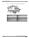
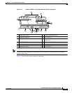
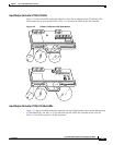
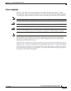
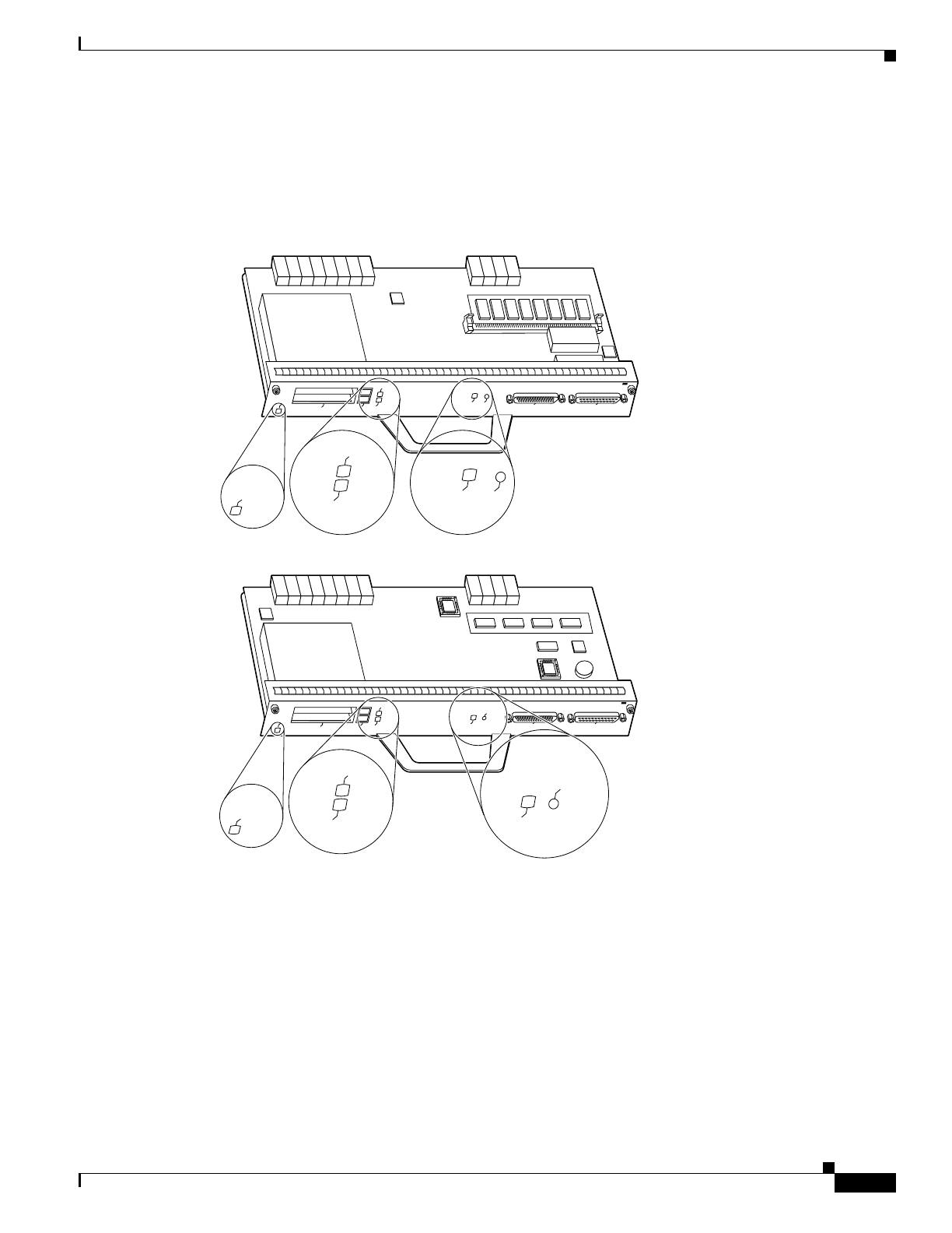
Figure 1-22 shows the LEDs on the I/O controller model with no Ethernet ports (C7200-I/O). This
I/O controller has no port-specific LEDs. Table 1-24 describes the LEDs on this I/O controller.
Figure 1-22 C7200-I/O LEDs and CPU Reset Button
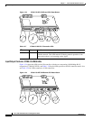
Input/Output Controller C7200-I/O-GE+E LEDs
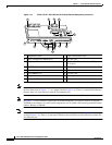
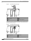
Figure 1-23 shows the LEDs on the I/O controller with the Gigabit Ethernet port and the Ethernet port
(C7200-I/O-GE+E), and Table 1-27 lists the LEDs specific to this I/O controller model. Also see
Table 1-24 for LEDs common to all I/O controllers.
AUX
CONSOLE
PCMCIA
EJECT
SLOT 0
CPU RESET
IO POWER
OK
SLOT 1
INPUT/OUTPUT CONTROLLER
H7401
SLOT 0
SLOT 1
CPU RESET
IO POWER
OK
ENABLED
ENABLED
AUX
CONSOLE
PCMCIA
EJECT
SLOT 0
I/O PWR
OK
SLOT 1
INPUT/OUTPUT CONTROLLER
25930
SLOT 0
SLOT 1
CPU RESET
I/O PWR
OK
ENABLED
ENABLED
CPU RESET