


1-15
Cisco 7200 VXR Installation and Configuration Guide
OL-5013-08
Chapter 1 Cisco 7200 VXR Product Overview
Field-Replaceable Units
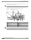
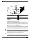
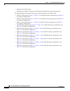
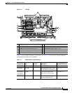
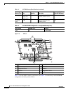
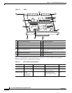
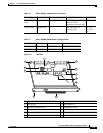
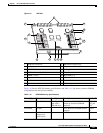
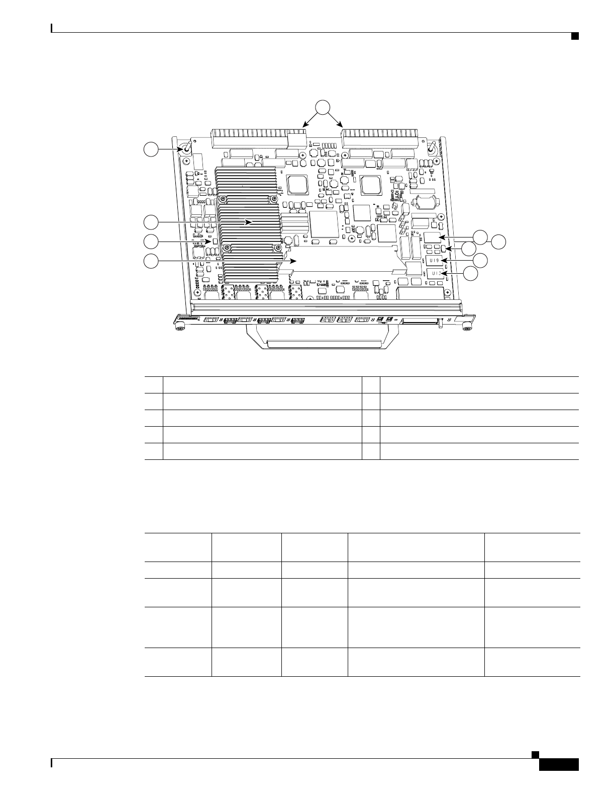
Figure 1-5 NPE-G2
Table 1-2 lists the NPE-G2 memory specification, and Table 1-3 lists the factory-installed SDRAM
configurations and their product numbers.
1 Midplane connectors 6 Flash memory (U13)
2 Boot ROM (U24) 7 DIMM (socket—S1)
3 NVRAM (on bottom of board—U17) 8 Temperature sensor (inlet—U23)
4 Temperature sensor (outlet—U20) 9 Processor (U30)
5 Flash memory (U19) 10 Keying post
149061
3
1
9
7
8
10
2
5
6
4
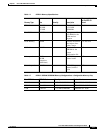
Table 1-2 NPE-G2 Memory Specifications
Memory Type Size Quantity Description
Component Location
on the NPE-G2 Board
SDRAM 1 GB 1 1-GB DDR SDRAM S1
Boot ROM 512 KB 1 Reprogrammable Boot ROM
for the ROM monitor program
U24
Flashmemory
(also known
as bootflash)
64 MB 1 Contains the default boot
helper (boot loader) image
U19 and U13
NVRAM 2 MB 1 Nonvolatile EPROM for the
system configuration file
U17