


1-21
Cisco 7200 VXR Installation and Configuration Guide
OL-5013-08
Chapter 1 Cisco 7200 VXR Product Overview
Field-Replaceable Units
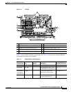
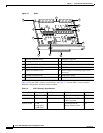
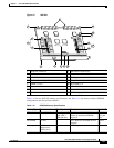
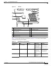
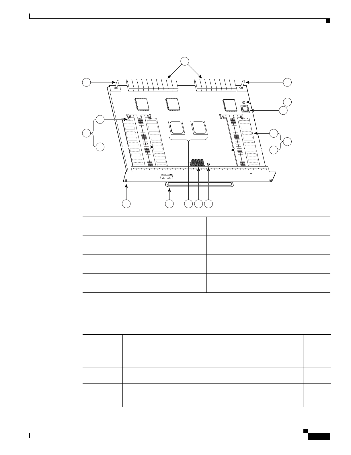
Figure 1-9 NPE-300
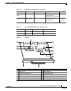
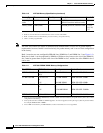
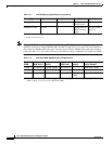
Table 1-10 lists the NPE-300 memory specifications, and Table 1-11 lists factory-installed SDRAM
configurations and their product numbers.
1 Midplane connectors 9 RM7000 microprocessor
2 Keying post 10 Temperature sensor (U42)
3 DIMM 3 (U44) 11 Keying post
4 Bank 1 (user configurable) 12 Temperature sensor
5 DIMM 2 (U45) 13 Boot ROM (U1)
6 Captive installation screw 14 DIMM 0 (U16)
7 Handle 15 Bank 0 (fixed size)
8 System controllers 16 U15 never populated
66410
NETWORK PROCESSING ENGINE-300
11
2
1
12
13
3
4
5
14
15
16
109876
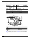
Table 1-10 NPE-300 Memory Specifications
Memory Type Size Quantity Description Location
1
SDRAM 32 to 256 MB 1 configurable
2
bank with 2
SDRAM slots
32-, 64-, or 128-MB DIMMs
(based on maximum SDRAM
required)
Bank 1:
U45 and
U44
3
Boot ROM 512 KB 1 OTP
4
ROM for the ROM monitor
program
Socket
U1
Primary cache 16 KB
(instruction),
16 KB (data)
— RM7000 processor, internal cache U49