


1-48
Cisco 7200 VXR Installation and Configuration Guide
OL-5013-08
Chapter 1 Cisco 7200 VXR Product Overview
Field-Replaceable Units
Note The port adapters installed in the Cisco 7200 VXR routers support OIR. For an explanation of OIR, see
the “Online Insertion and Removal” section on page 1-57.
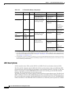
All port adapters and service adapters connect to two Peripheral Component Interconnect (PCI) buses
on the router midplane. The PCI buses provide a path to packet I/O memory and the system
(route/switch) processor. The Fast Ethernet port on the I/O controller connects to a third PCI bus for
packet routing and switching. The port or service adapters either provide such services as compression
or encryption, or they provide network interfaces to connect the router to external networks.
Note Detailed instructions for removing, replacing, and configuring the port adapter types supported on the
Cisco 7200 VXR routers are contained in the configuration note for the port adapter. For example, if you
plan to replace a 4-port Ethernet port adapter in your Cisco 7200 VXR router, refer to the configuration
note PA-4E Ethernet 10BaseT Port Adapter Installation and Configuration. The configuration note is
available on the Documentation DVD and on Cisco.com.
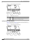
Caution To ensure adequate airflow across the router’s port adapters, a port adapter or a blank port adapter must
be installed in each port adapter slot.
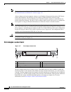
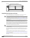
Port Adapter Jacket Card
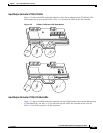
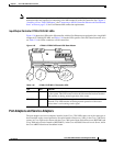
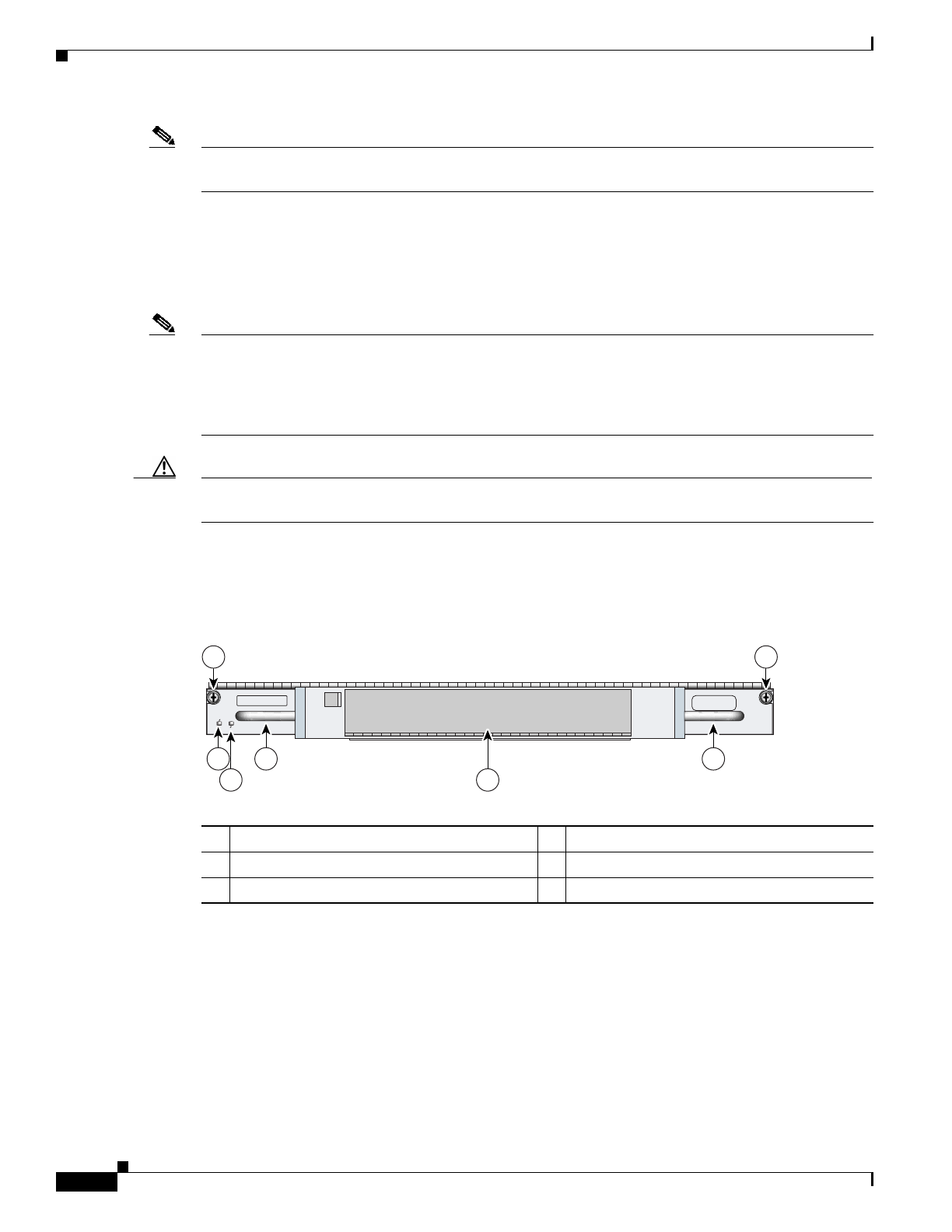
Figure 1-27 Port Adapter Jacket Card
The Port Adapter Jacket Card is used in a Cisco 7200 VXR router only with an NPE-G1 or NPE-G2
installed and with no I/O controller. The NPE-G1 has I/O controller functionality, so no I/O controller
is needed. The Port Adapter Jacket Card installs in the I/O controller slot, and provides for an additional
port adapter slot. The Port Adapter Jacket Card works from a third PCI bus, which provides additional
bandwidth and virtually unlimited bandwidth points to the single port adapter slot. For more
information, see the Port Adapter Jacket Card Installation Guide.
1 Captive installation screw 4 Handle
2 ENABLE LED 5 Port adapter slot
3 PWR (power) LED
138883
PORT ADAPTER JACKET CARD
ENABLED
PWR
3
2 4
5
1
4
1