


1-37
Cisco 7200 VXR Installation and Configuration Guide
OL-5013-08
Chapter 1 Cisco 7200 VXR Product Overview
Field-Replaceable Units
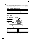
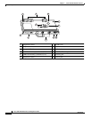
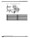
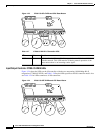
Note In n Figure 1-20, the NVRAM is replaced by an SRAM component (U14) that is made to act like the
NVRAM by the addition of some external components, one of which is the button-type lithium battery
labeled “Battery for SRAM.”
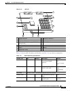
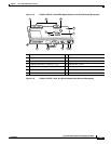
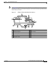
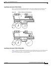
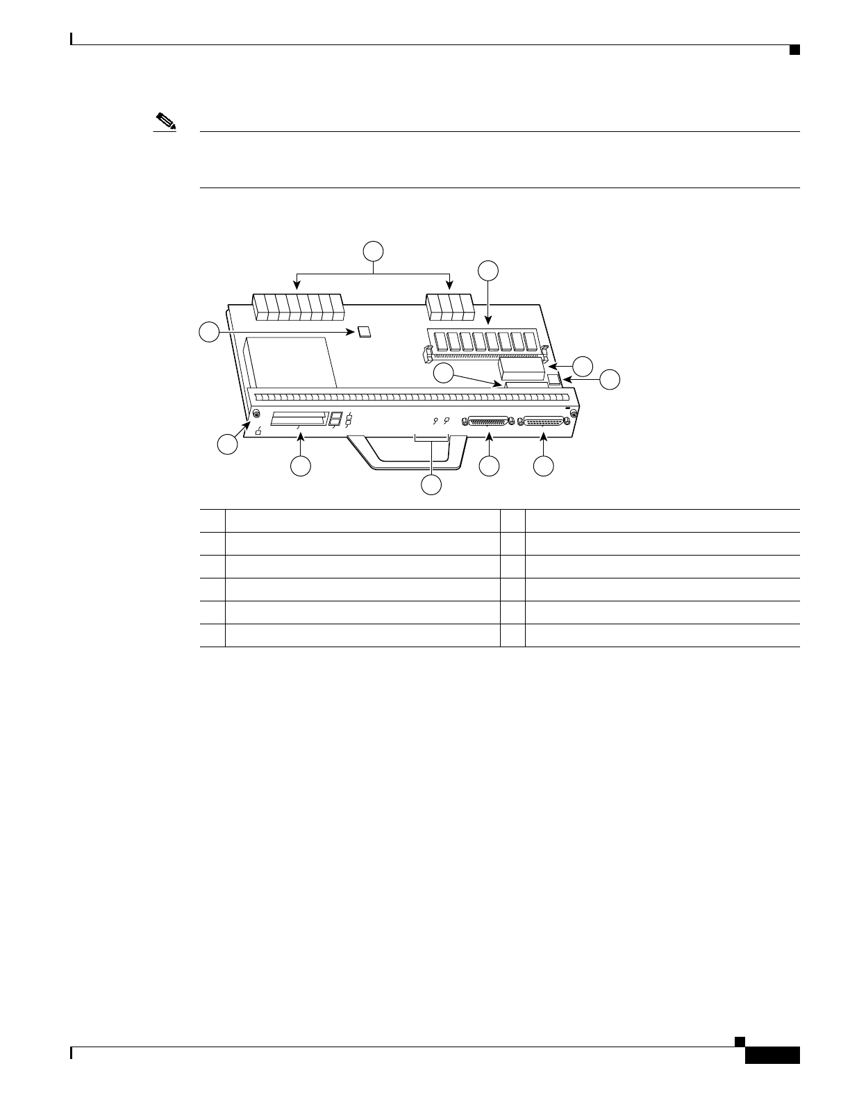
Figure 1-19 C7200-I/O—Without Fast Ethernet Port (Version 1)
1 Temperature sensor 7 Captive installation screw
2 Midplane connectors 8 PC Card slots
3 Flash SIMM (U99) 9 LED and CPU reset button
4 Boot ROM (U20) 10 Auxiliary port
5 NVRAM (U41) 11 Console port
6 Temperature sensor
93277
CPU RESET
IO PWR OK
AUX
CONSOLE
PCMCIA
EJECT
SLOT 0
SLOT 1
FAST ETHERNET INPUT/OUTPUT CONTROLLER
ENABLED
8
7
1110
1
4
3
5
6
2
9