


1-5
Cisco 7200 VXR Installation and Configuration Guide
OL-5013-08
Chapter 1 Cisco 7200 VXR Product Overview
Cisco 7204VXR Overview
With the NPE-G1 or NPE-G2 installed and the Port Adapter Jacket Card installed in the I/O controller
slot, an additional port adapter slot is available.
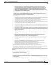
Note If you have difficulty installing a processing engine or I/O controller in the lowest slot of a
Cisco 7200 VXR router that is rack-mounted, remove the port adapters, processing engine and I/O
controller from the chassis and reinstall them. Install the processing engine and I/O controller in the
lowest slots first, then populate the slots above them, in a bottom-to-top order.
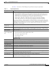
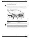
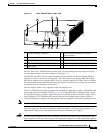
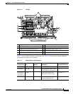
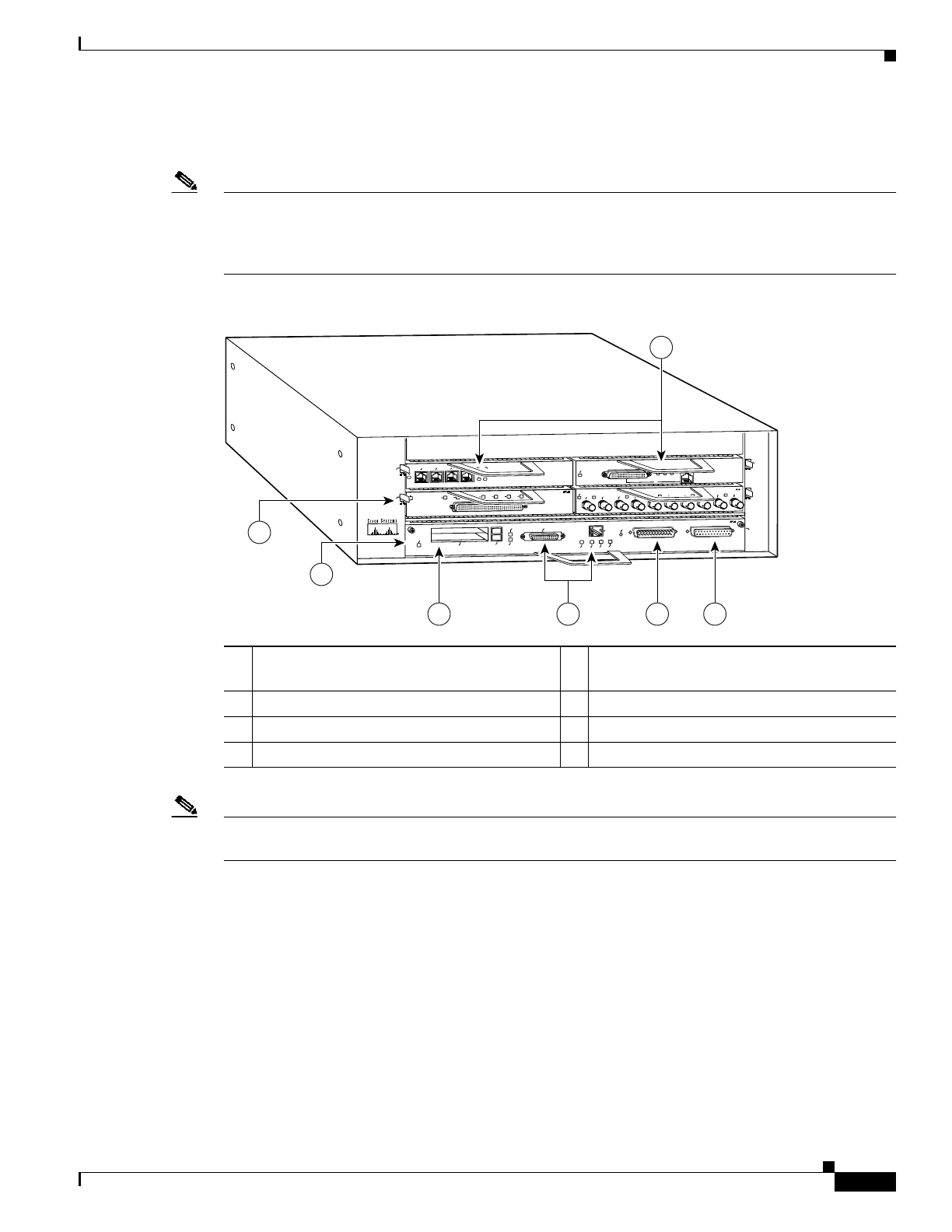
Figure 1-1 Cisco 7204VXR Router—Front View
Note In Figure 1-1, a blank port adapter is installed in slot 3. To ensure adequate airflow across the port
adapters, each port adapter slot must be filled with either a port adapter or a blank port adapter.
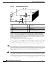
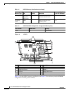
The rear of the Cisco 7204VXR router provides access to the network processing engine or network
services engine and up to two power supplies. (See Figure 1-2.)
1 Port adapters 5 Optional Fast Ethernet interface (MII portand
RJ-45 port)
2 Port adapter lever 6 Auxiliary port
3 I/O controller 7 Console port
4 PC Card slots
2
ETHERNET-10BFL
EN
RX
0
1
2
3
4
TX
RX
TX
RX
TX
RX
TX
RX
TX
Cisco 7200
SERIES
XVR
0
4
1
3
EN
0
7
1
2
3
4
5
6
SERIAL-EIA/TIA-232
MII
EN
RJ45
EN
RJ45
LINK
1O PWR
OK
RJ-45
CPU RESET
FAST ETHERNET INPUT/OUTPUT CONTROLLER
ENABLED
PCMCIA
EJECT
SLOT 0
SLOT 1
FE MII
ETHERNET 10BT
ENABLED
0
2
1
3
LINK
0
1
2
3
ENABLED
MII
LINK
RJ45
FAST ETHERNET
0
15889
1
2
3
64 75