


1-40
Cisco 7200 VXR Installation and Configuration Guide
OL-5013-08
Chapter 1 Cisco 7200 VXR Product Overview
Field-Replaceable Units
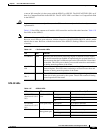
LED Descriptions
All I/O controllers have LEDs, and the NPE-G1 and NPE-G2 also have interfaces that have LEDs.
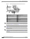
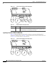
The I/O controller faceplate contains LEDs that indicate system and port status; two additional LEDs
indicate the status of the Flash Disk or Flash memory cards installed in either PC Card slot. A CPU reset
button is located next to the IO POWER OK LED or next to the auxiliary port on the I/O controller
faceplate. The CPU reset button resets the entire system.
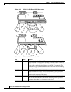
The NPE-G2 and NPE-G1 faceplate contains LEDs that indicate system and port status. The RJ-45 and
GBIC or SFP ports share the same LINK LED because only one of these ports per interface (0/1, 0/2, or
0/3) can be used at any one time. The ENABLE LED is on if the RJ-45 port is in use. The POWER ON
LED on the NPE-G1 or the PWR OK LED on the NPE-G2 is on when the system is powered on, whether
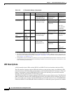
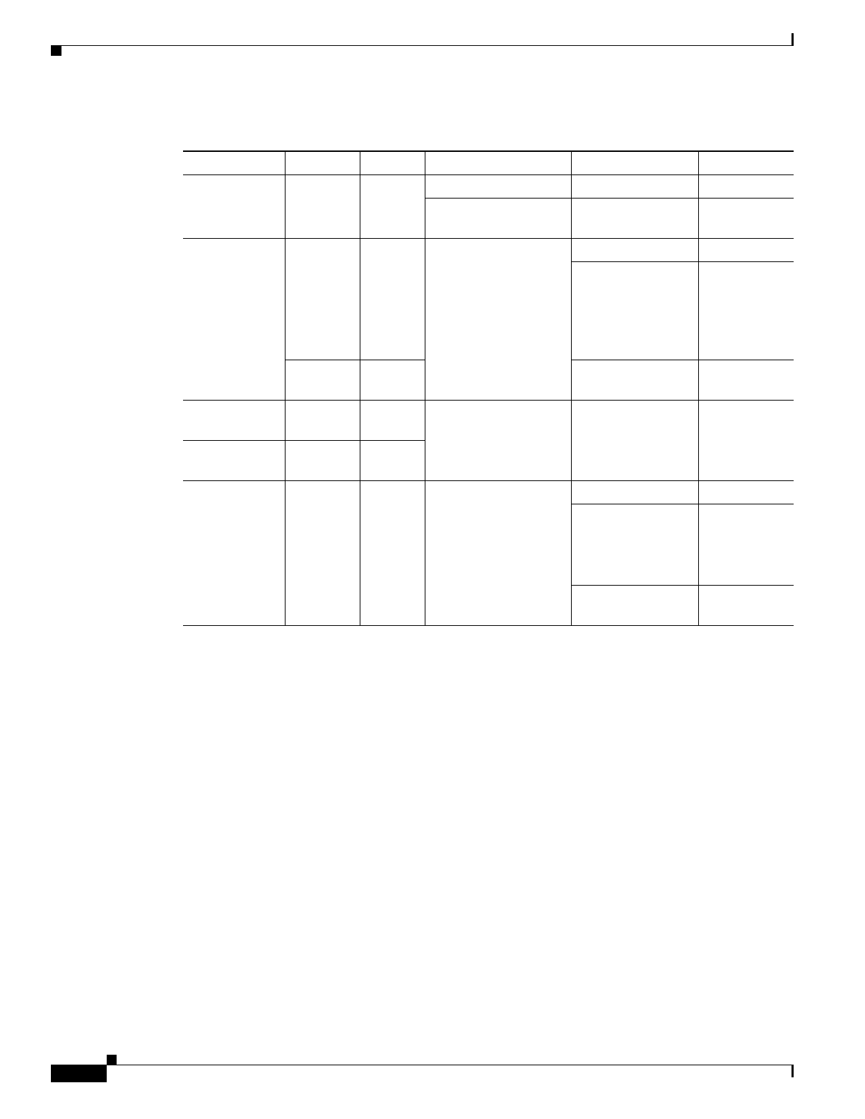
Table 1-23 I/O Controller Memory Components
Type Size Quantity Memory Description Model Location
Boot ROM
1
1. The C7200-I/O-GE+E and C7200-I/O-2FE/E do not have a boot ROM component.
256 KB 1 32-pin DIP-type C7200-I/O-FE-MII U20
32-pin DIP-type or
32-pin PLCC-type
C7200-I/O-FE,
C7200-I/O
U20 or U4
Flash memory 4 MB 1 Contains the default
boot helper image
C7200-I/O-FE-MII U99
C7200-I/O-FE,
C7200-I/O
U99
or
U10, U11,
U12, and U13
(soldered)
2
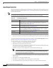
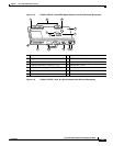
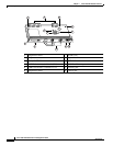
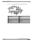
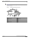
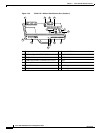
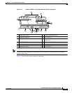
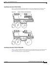
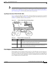
2. Some I/O controllers have no Flash SIMM but use a permanently soldered 4-MB or 8-MB Flash memory chip instead. (For
thelocation ofthe 4-MBFlash memory chip,see theFigure 1-18 andFigure 1-20. Forthe locationof the8-MB Flashmemory
chip, see Figure 1-15 and Figure 1-16.)
8 MB 1 C7200-I/O-GE+E,
C7200-I/O-2FE/E
U13 and U25
(soldered)
2
Flash memory
card
16 or
20 MB
Up to 2 Contains the default
Cisco IOS image
All models PCCardslot 0
and slot 1
Flash Disk 32, 48, or
128 MB
Up to 2
NVRAM 128 KB 1 Nonvolatile EPROM
for the system
configuration file
C7200-I/O-FE-MII U41
C7200-I/O-FE,
C7200-I/O
U41
or
U14
(soldered)
3
3. The NVRAM on some I/O controllers is replaced by a 32-pin nonsocketed SRAM component that is soldered onto the card.
The SRAMcomponent is made toact likethe NVRAMby theaddition ofsome externalcomponents, oneof whichis a1-inch
(2.54-cm) button-type lithium battery.
C7200-I/O-GE+E,
C7200-I/O-2FE/E
U19
(soldered)
3