


1-25
Cisco 7200 VXR Installation and Configuration Guide
OL-5013-08
Chapter 1 Cisco 7200 VXR Product Overview
Field-Replaceable Units
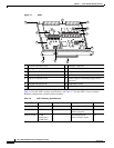
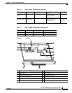
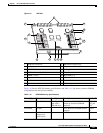
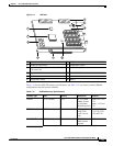
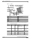
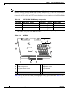
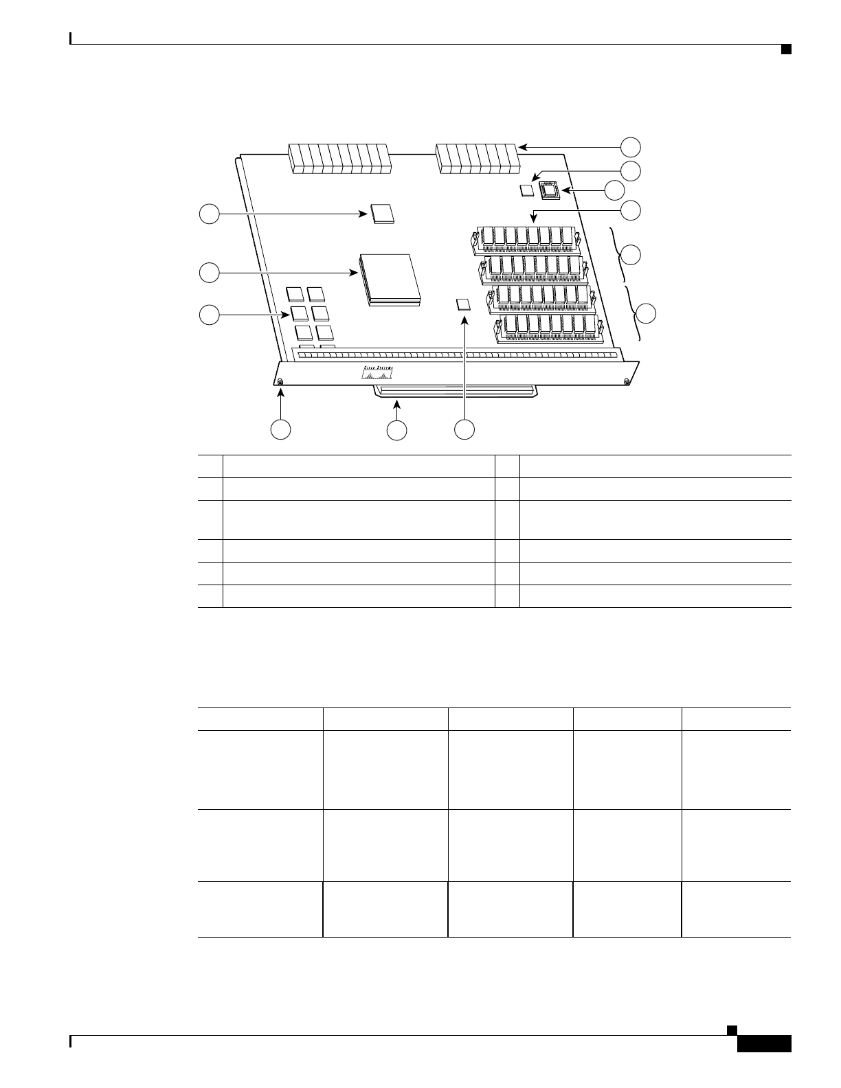
Figure 1-11 NPE-200
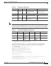
Table 1-14 lists the NPE-200 memory specifications, and Table 1-15 lists factory-installed DRAM
configurations and their product numbers.
1 System controller 7 Midplane connectors
2 R5000 microprocessor 8 Temperature sensor
3 4-MB SRAM (U6, U10, U13, U14,U28, U29,
U38, and U39)
9 Boot ROM (U92)
4 Captive installation screw 10 DRAM SIMMs
5 Handle 11 Bank 1
6 Temperature sensor 12 Bank 2
66420
U52
U42
U25
U11
NETWORK PROCESSING ENGINE-200
7
11
10
8
12
4 6
5
3
2
1
9
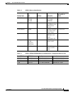
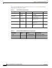
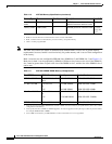
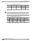
Table 1-14 NPE-200 Memory Specifications
Memory Type Size Quantity Description Location
1
DRAM 32 to 128 MB 2 to 4 16- or 32-MB
SIMMs (based
on maximum
DRAM required)
Bank 0: U11 and
U25
Bank 1: U42 and
U52
SRAM 4 MB 8 8 chips, each
being 512K
words x 8 bits
wide
U6, U10, U13,
U14, U28, U29,
U38, and U39
Boot ROM
2
256 KB 1 EPROM for the
ROM monitor
program
U92