


1-54
Cisco 7200 VXR Installation and Configuration Guide
OL-5013-08
Chapter 1 Cisco 7200 VXR Product Overview
Functional Overview
Functional Overview
This section provides a functional overview of the Cisco 7200 VXR routers. It describes the numbering
and addressing scheme of the port adapters for the router, the environmental monitoring and reporting
functions, and online insertion and removal (OIR). These descriptions help you become familiar with
the capabilities of the Cisco 7200 VXR routers.
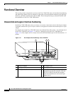
Chassis Slot and Logical Interface Numbering
In the Cisco 7200 VXR routers, the port-adapter-slot-number is the chassis slot in which a port adapter
is installed, whereas the logical-interface-number is the physical location of the interface port on a port
adapter.
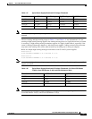
Port adapter slots in the Cisco 7200 VXR routers are numbered from left to right— slot 1 through slot 4
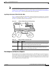
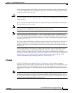
in the Cisco 7204VXR (see Figure 1-31) and slot 1 through slot 6 in the Cisco 7206VXR (see
Figure 1-32). Port adapter slot 0 is always reserved for the Fast Ethernet port on the I/O controller—if
present.
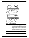
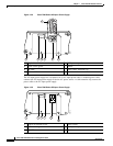
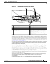
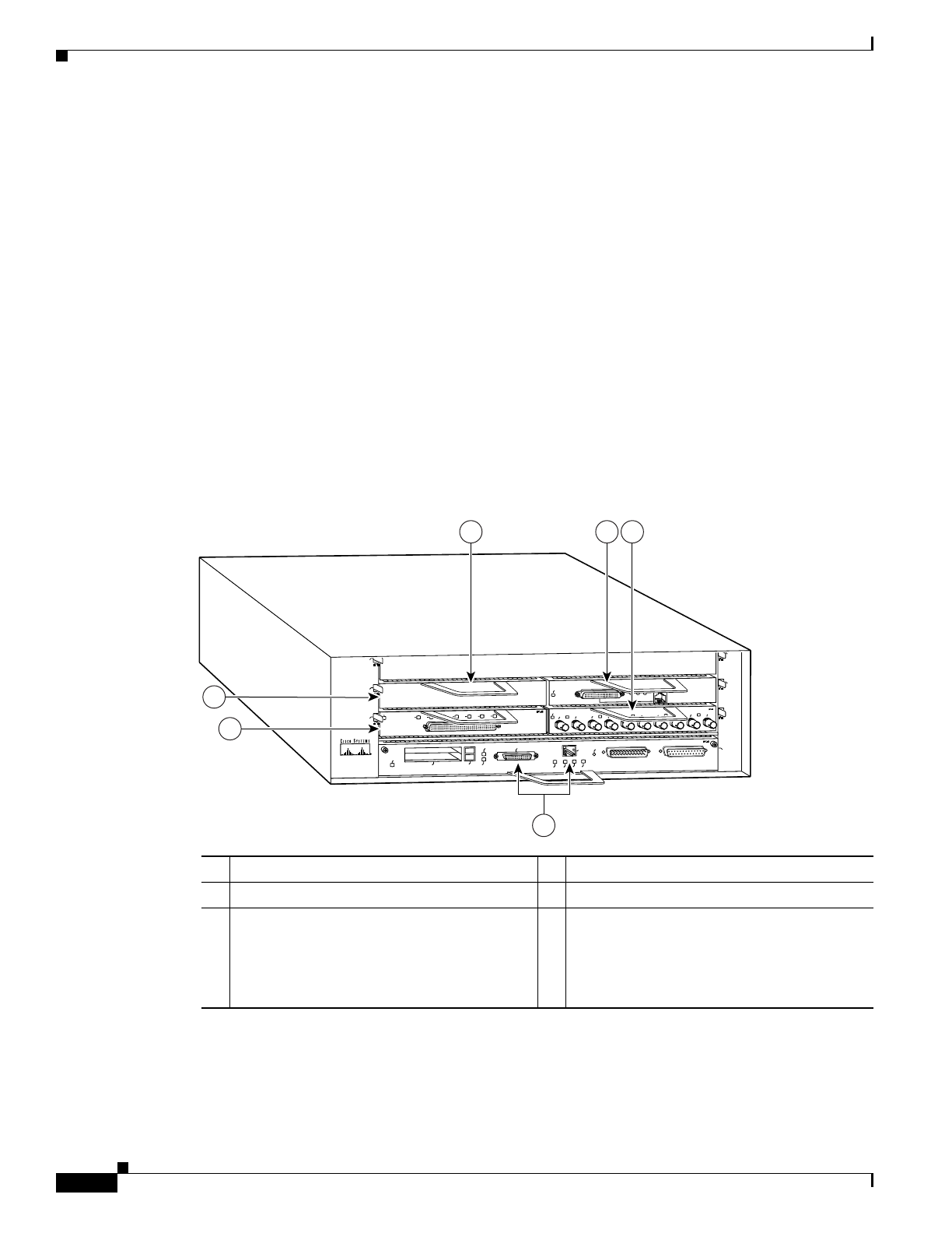
Figure 1-31 Port Adapter Slot Numbering—Cisco 7204VXR
1 Blank port adapter 4 Port adapter slot 3
2 Port adapter slot 4 5 Port adapter slot 1
3 Port adapter slot 2 6 Port adapter slot 0 (Reserved for the Fast
Ethernet port on the I/O controller. With the
NPE-G1 or NPE-G2 and the Port Adapter
Jacket Card installed, the slot becomes port
adapter slot 5.)
2
ETHERNET-10BFL
EN
RX
0
1
2
3
4
TX
RX
TX
RX
TX
RX
TX
RX
TX
0
4
1
3
5
6
EN
0
7
1
2
3
4
5
6
SERIAL-EIA/TIA-232
Cisco 7200
SERIES
MII
EN
RJ45
EN
RJ45
LINK
1O PWR
OK
RJ-45
CPU RESET
FAST ETHERNET INPUT/OUTPUT CONTROLLER
ENABLED
PCMCIA
EJECT
SLOT 0
SLOT 1
FE MII
ENABLED
MII
LINK
RJ45
FAST ETHERNET
0
84540
1 2 3
4
5
6